
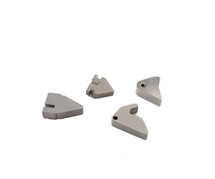
Product example
Spring Bolt and Latch Components
Compact latch forms with angled contact faces. Review engagement, return motion and the connection to the lock mechanism.
Lock and security components are the metal parts that carry the locking, guiding and contact functions in a lock — spring bolts, deadbolts, cylinder bodies and cores, levers, cam parts and smart-lock hardware. SINTS manufactures them by powder metallurgy (PM), metal injection molding (MIM) or machining, chosen by load path, wear surface and annual volume.
Compact latch forms with angled contact faces. Review engagement, return motion and the connection to the lock mechanism.
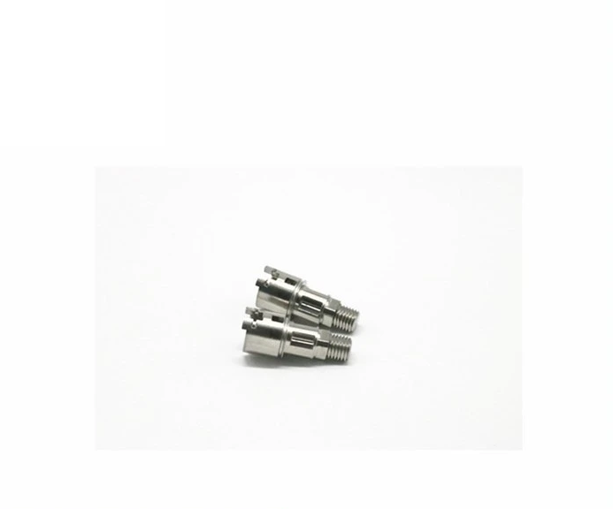
Cylindrical components with slots and stepped surfaces. Define the bore, axis and mating hardware from the lock assembly.
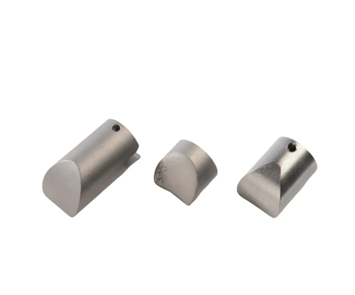
Locking elements with rounded and stepped profiles. Specify travel, support and engagement surfaces.
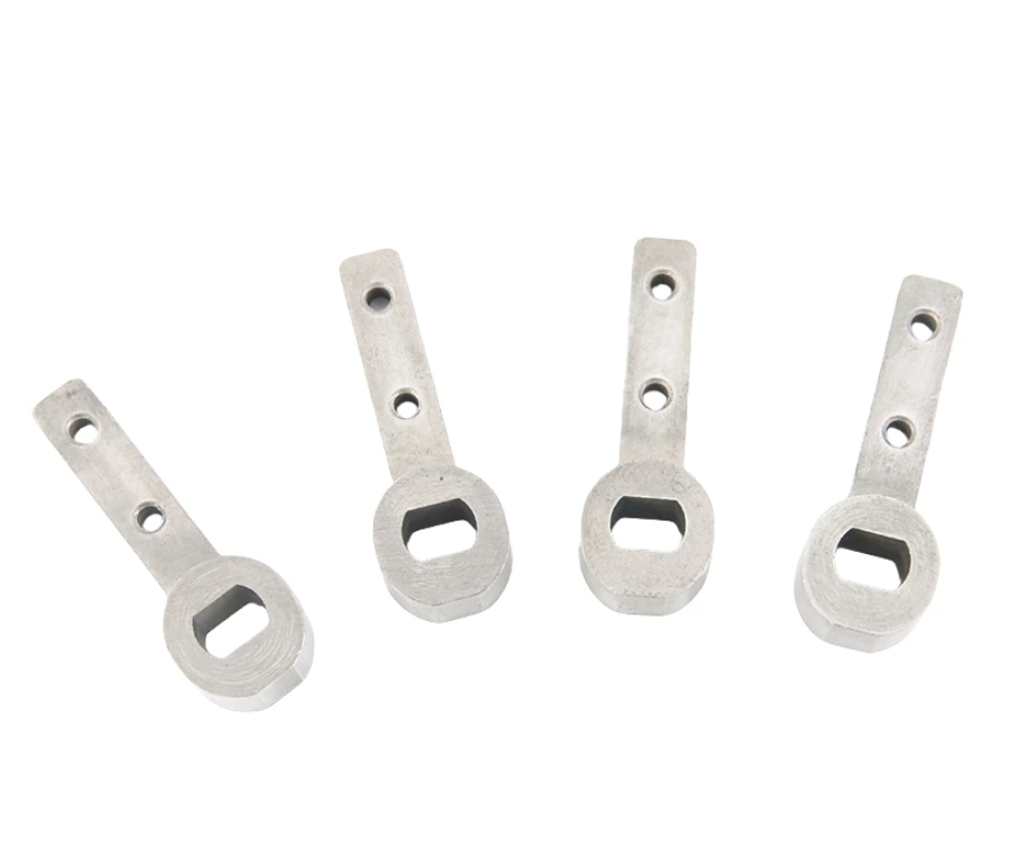
Lever-like components with connection holes. Hole spacing and the contact profile should follow the mating mechanism.
Examples from the SINTS product catalog, shown for component identification. These are custom parts, not stock specifications. Dimensions, material, supply scope and acceptance requirements are confirmed from your project drawing.
The part you see, the production behind itLock hardware components and the production line that makes them, filmed on the SINTS floor in Zhongshan.
Working travel, engagement surfaces, mating parts and return arrangement.
Contact load, lubrication, corrosion exposure and cleaning conditions.
Individual component or assembly, material condition and required finish.
Fit and operating tests, sample quantities and annual volume per variant.
Explore each component in detail, including its interfaces, manufacturing review and drawing requirements.
The spring-bolt examples show different contact profiles. For a similar part, share the relationship to the spring, actuator and lock body, including travel and guiding clearance. Contact surfaces, connecting holes and the final finish can then be reviewed against the required motion.
The cylinder reference contains stepped and slotted forms. Mark the functional axis and the surfaces that drive or retain the mating hardware. Agree dimensions and operating checks in the finished condition, including any coating or heat treatment specified by the project.
The part drawing and its assembly determine the manufacturing route and the inspection plan.
Lock-body fit, connection holes, travel and engagement geometry.
Return action, sliding contacts, cycle requirements and mating materials.
Appearance, corrosion requirements and dimensions after finishing.
Fit and action checks using the intended mating lock hardware.
Three reference tables for lock and security hardware: which grades are actually used and what they measure, where the two forming routes stop, and what the route from drawing to first article looks like.
| Grade | Condition | Yield / UTS (MPa) | Elong. | Hardness | Density (g/cm³) | Why it is used here |
|---|---|---|---|---|---|---|
| 316L | Sintered | 250 / 498 | 40% | 110–160 HV | 7.75 | Outdoor and marine locks. The highest salt-spray headroom of the austenitic grades (72–120 h neutral, 200–500 h after passivation) and still soft enough to roll a thread. |
| 304 | Sintered | 270 / 480 | 35% | 110–160 HV | 7.65 | Indoor cylinders, housings and trim, where chloride exposure is low and feedstock cost decides. |
| 17-4PH | Sintered → H900 aged | 720 / 900 → 1070 / 1160 | 11% → 7% | 20–25 → 35–45 HRC | 7.50 | Security-critical bolts, cams and drive parts that need strength without giving up corrosion resistance. |
| 420 | Heat treated | 1150 / 1310 | 6% | 40–45 HRC | 7.40 | Latch noses, strike plates and wear faces: hard enough for repeated cycling, still machinable for the final fit. |
| 440C | Sintered | 1550 / 1750 | 1% | 58–62 HRC | 7.50 | The wear extreme. Chosen when abrasion rather than impact is the failure mode, and accepted where 1% elongation is tolerable. |
| 4605 (Fe-2Ni) | Sintered → heat treated | 500 / 700 → 1425 / 1610 | 11% → 3% | 70–100 HRB → 45–50 HRC | 7.50 | Cost-driven internal structure parts. Salt spray is not stated for this grade, so corrosion resistance has to come from a coating. |
Yield / UTS in MPa, elongation in %, hardness and density (g/cm³) are reference ranges from the SINTS material summary, not guaranteed minima for a specific part. Heat-treated values depend on the cycle agreed for the program. Cost is excluded here on purpose — it belongs in the quotation, not on a page.
| Requirement | Powder compaction | MIM | What it means here |
|---|---|---|---|
| Minimum wall section | Set by fill, ejection and green strength; reviewed per part | 1–3 mm works comfortably; below about 0.5 mm cavity fill is at risk | Lock covers, escutcheons and thin latch plates sit at the low end of both routes |
| General dimension, as sintered | Roughly ±0.3–0.5% of the dimension | Roughly ±0.3–0.5% of the dimension | A 20 mm cylinder bore carries about ±0.06–0.10 mm before any sizing |
| Features tighter than about ±0.05 mm | Sizing or machining | Machining after sintering | Keyways, pin holes and detent grooves are normally sized rather than pressed to final |
| Density and thread forming | Needs ≥7.0 g/cm³ for a rolled thread | Same threshold | Below it the thread is cut instead of rolled, and the unit cost structure changes with it |
| Wear surface integrity | Density follows compacting pressure and mass distribution | Same, with more freedom in geometry | A hard alloy at low density wears faster than a softer alloy at full density |
| Economic volume | Tooling-led; reviewed against annual demand | Tooling-led; reviewed against annual demand | As a rule of thumb, below a few thousand pieces a year the tooling rarely pays back on a lock part |
The percentage figures follow the tolerance discussion already published in the MIM tolerances and design guidelines note: they are planning arithmetic, not an achieved capability. Absolute tolerance changes with feature size, so a small bore and a long housing built to the same percentage do not hold the same value.
| Stage | Typical lead time | What you receive | What we need from you |
|---|---|---|---|
| Drawing review and DFM feedback | Issued with the quotation | Feature-by-feature route proposal, tolerance and finishing notes, and the open points that must be answered before tooling | 2D drawing with tolerances and datums, STEP model, target annual volume, material or the performance requirement |
| Tooling | 25–30 days as quoted on recent programs | Mould or die built and released to trial condition | Approval of the DFM report and confirmation of the alloy |
| T0 samples | 7–10 days after tooling release as quoted on recent programs | Parts plus a dimensional report against the drawing | Agreed inspection plan and datum scheme |
| Sizing, finishing and heat treatment | Runs inside or immediately after the sample stage | Sized and finished parts, hardness and density results where specified | Which features must be held after sintering, and which may be finished |
| First-article report | With the first approved samples | Dimensions, material, hardness and density measured in-house rather than subcontracted | Drawing with the critical characteristics marked |
| Production release | After sample approval | Serial production to the agreed inspection plan | Confirmed annual volume, MOQ and packaging |
Tooling and sample durations above are the lead times quoted on recent programs of comparable size, not a standard promise; the schedule for a specific part is confirmed with its quotation. Every result in the first-article report is measured on the instruments listed on the capabilities page.
Lock and security components carry the locking, guiding and contact functions in a lock. These answers cover process selection, wear surfaces, security boundaries and documentation.
Repeat-volume parts that combine a simple structural form with a small amount of genuine three-dimensional detail are the usual targets: spring bolts, latch and cam parts, cylinder bodies and cores, levers, guides and small retention hardware. The decision then turns on the load the part carries, the surface that wears and whether the part is a security-critical element.
A locking mechanism is a repeated-cycle mechanism, so the surfaces that slide, engage or carry the bolt usually decide the part's service life. Hardness, surface condition, density and lubrication all affect how those surfaces behave, which means a part can be structurally adequate yet still unsuitable if its contact surfaces are not controlled. Those interfaces belong on the drawing as requirements, not as outcomes.
That is a decision the customer makes, not the manufacturer. SINTS reviews whether a component can be produced to the stated geometry, material and volume, and which route fits. SINTS does not certify or validate the security rating of a lock, and any security, pick-resistance or attack-resistance testing remains the customer's own responsibility and risk assessment.
Start with the axis and the engagement features. The cylinder body or core carries the keyway or pin interface, a rotational datum and a set of engagement features that must align with the rest of the lock, so concentricity, axial datum and the tolerance on the engagement surfaces matter more at screening stage than overall dimensions. Those features are what the process has to hold.
Send the drawing, the part's role in the locking chain, the load or force it carries, the surface that wears or engages, the required hardness or surface condition, the material of mating parts, annual volume and any documentation the program needs. That combination is what allows a manufacturing review rather than a process guess.
Include the lock assembly, motion or travel, guiding fits, finish requirements and planned production quantity.
These are review inputs, not fixed catalog specifications. Supply the drawing revision and identify any requirements still to be confirmed.