
When is MIM a good fit?
MIM may fit small, complex 3D metal parts when geometry consolidation and repeat volume justify tooling. Material, distortion risk, critical datums and secondary finishing still need drawing-level review.
Custom metal components for OEM programs, made to your drawing. We review MIM, powder metallurgy, gears and secondary machining against your geometry, material, quantity and critical requirements.
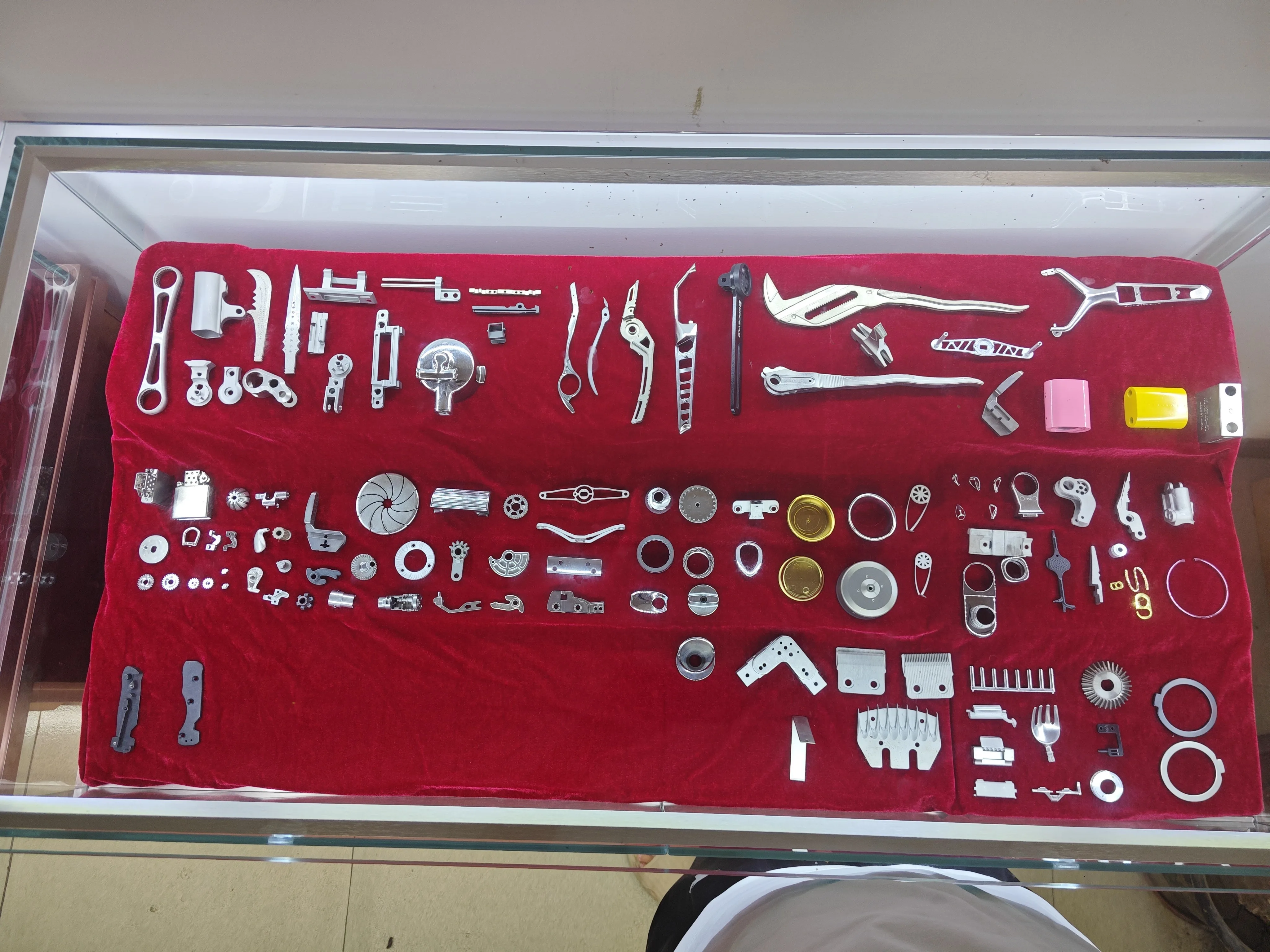
Browse real product examples for familiar applications, or start with a custom OEM drawing.
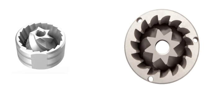
Grinder burrs, portafilter hardware and appliance mechanisms
View examples →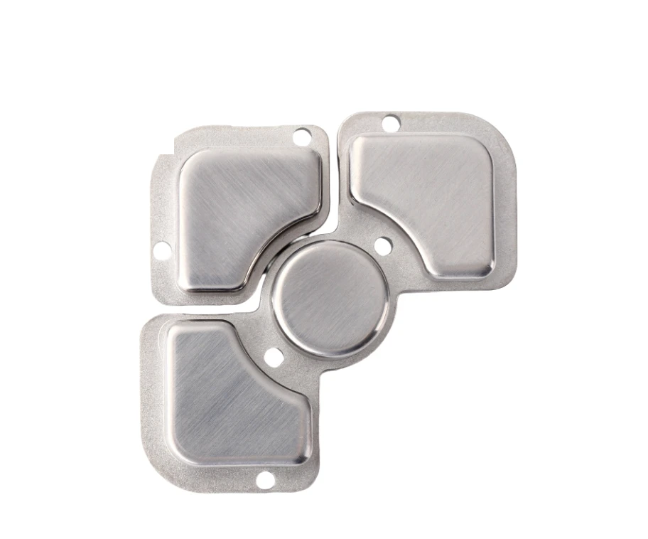
Buttons, communication-device parts, watch and camera hardware
View examples →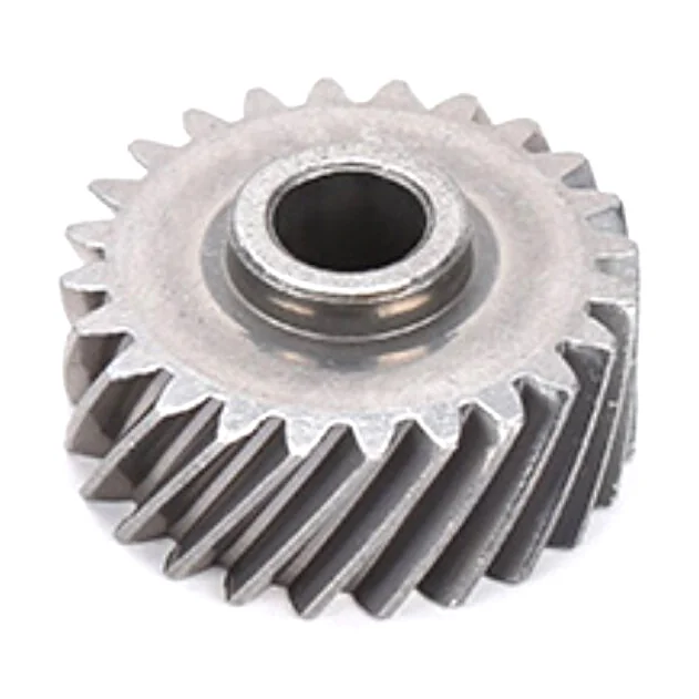
Spur, helical and bevel gears, plus supporting bushings
View examples →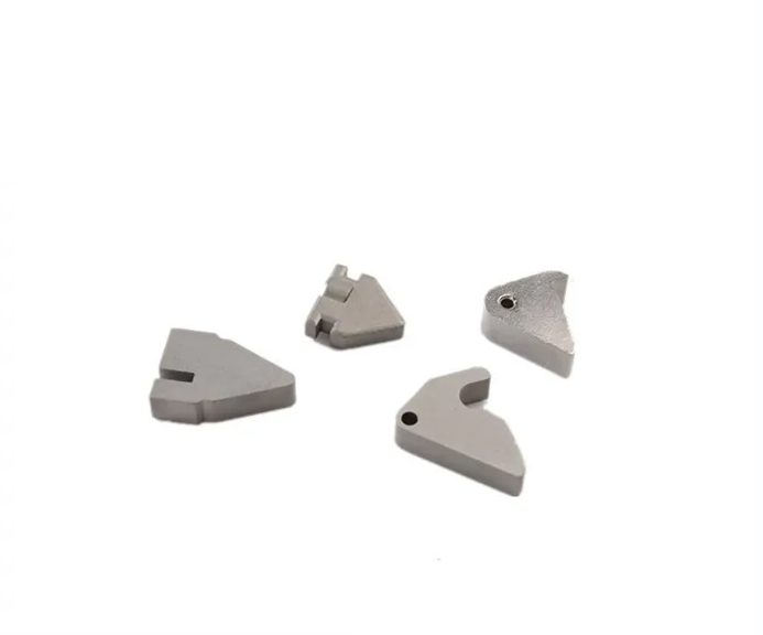
Spring bolts, deadbolts, cylinder parts and smart-lock hardware
View examples →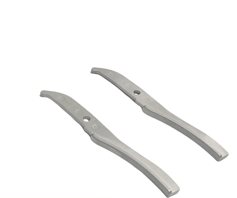
Forceps, tweezer and instrument component examples
View examples →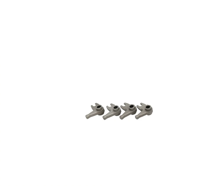
Tool gears, pneumatic forks, guide components and hardware
View examples →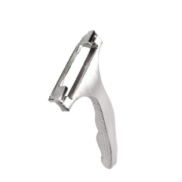
Agricultural, personal-care and drawing-specific metal parts
View examples →Review molding, sintering and the features that may need finishing.
Read the guide →PMDiscuss compaction geometry, material condition and final interfaces.
Read the guide →GearsStart with the teeth, mating surfaces, load and acceptance requirements.
Read the guide →From gears and bushings to bolts, hinges and compact mechanisms, SINTS produces metal components to customer drawings. Engineering support covers tooling, forming, secondary operations and inspection.
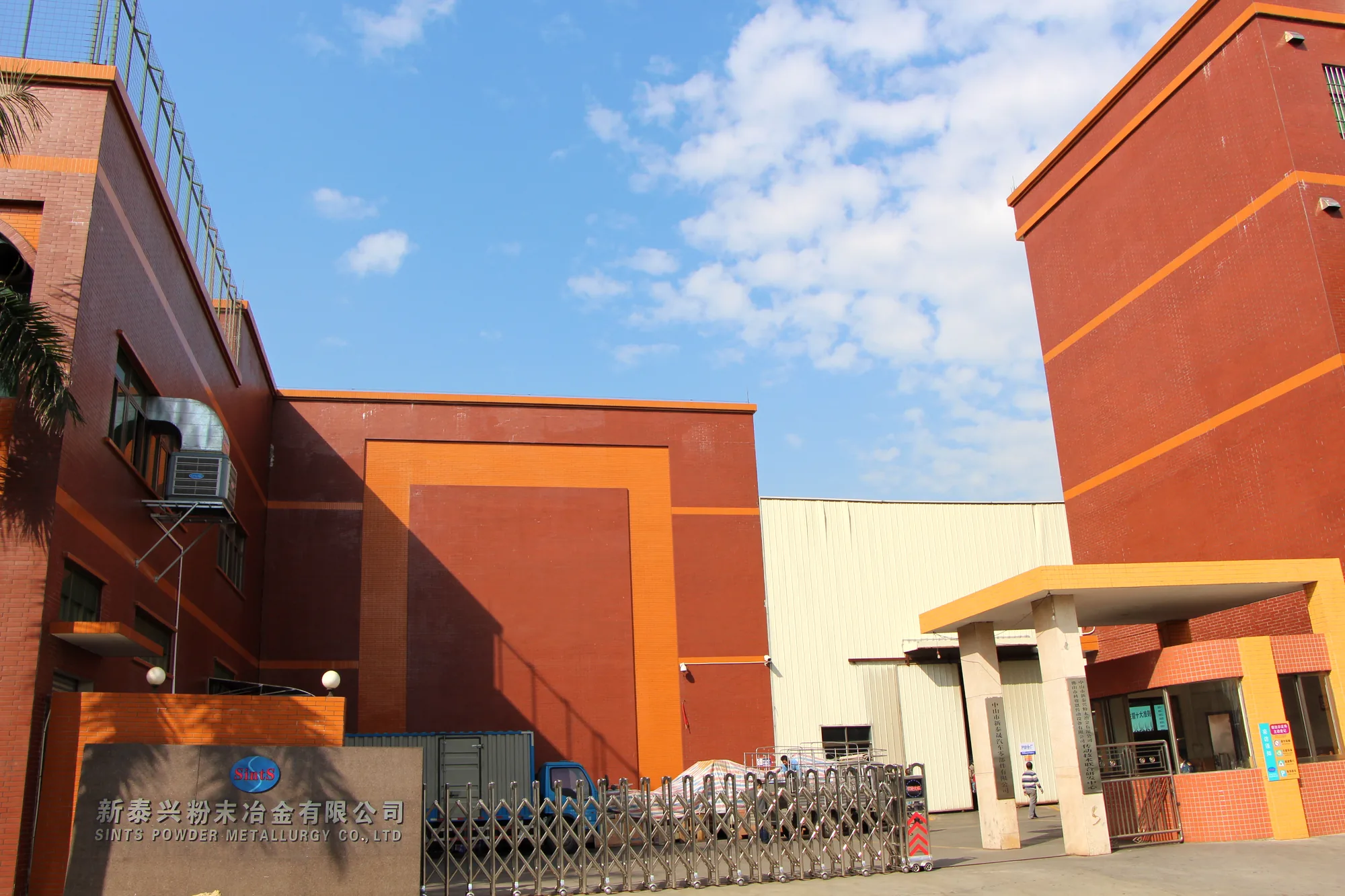
The Zhongshan and Jiangxi production bases provide about 45,000 m² of combined manufacturing area. For new programs, the engineering discussion starts with part function, geometry, material, critical datums, load or wear conditions, annual demand and the surfaces that may need secondary control.
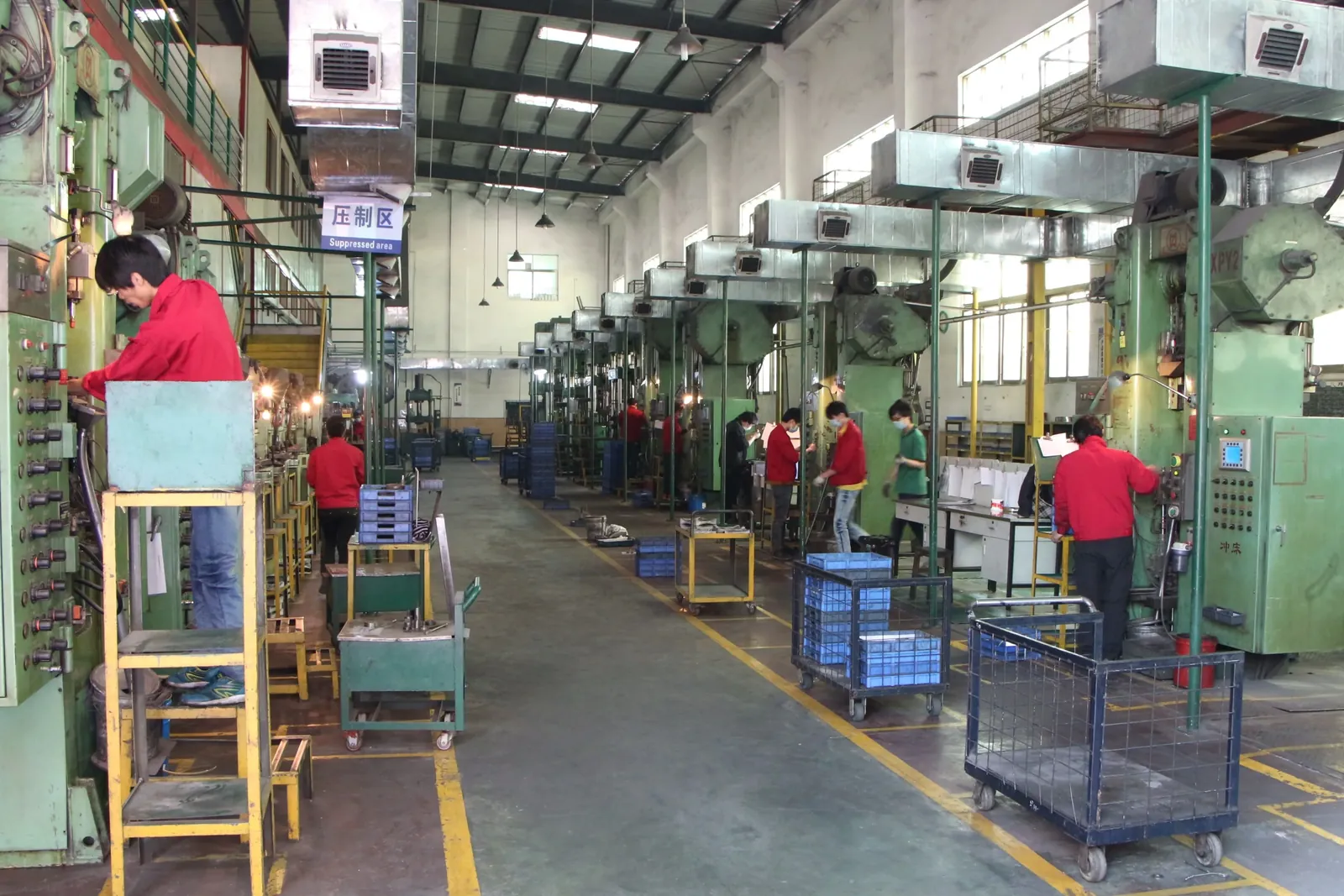
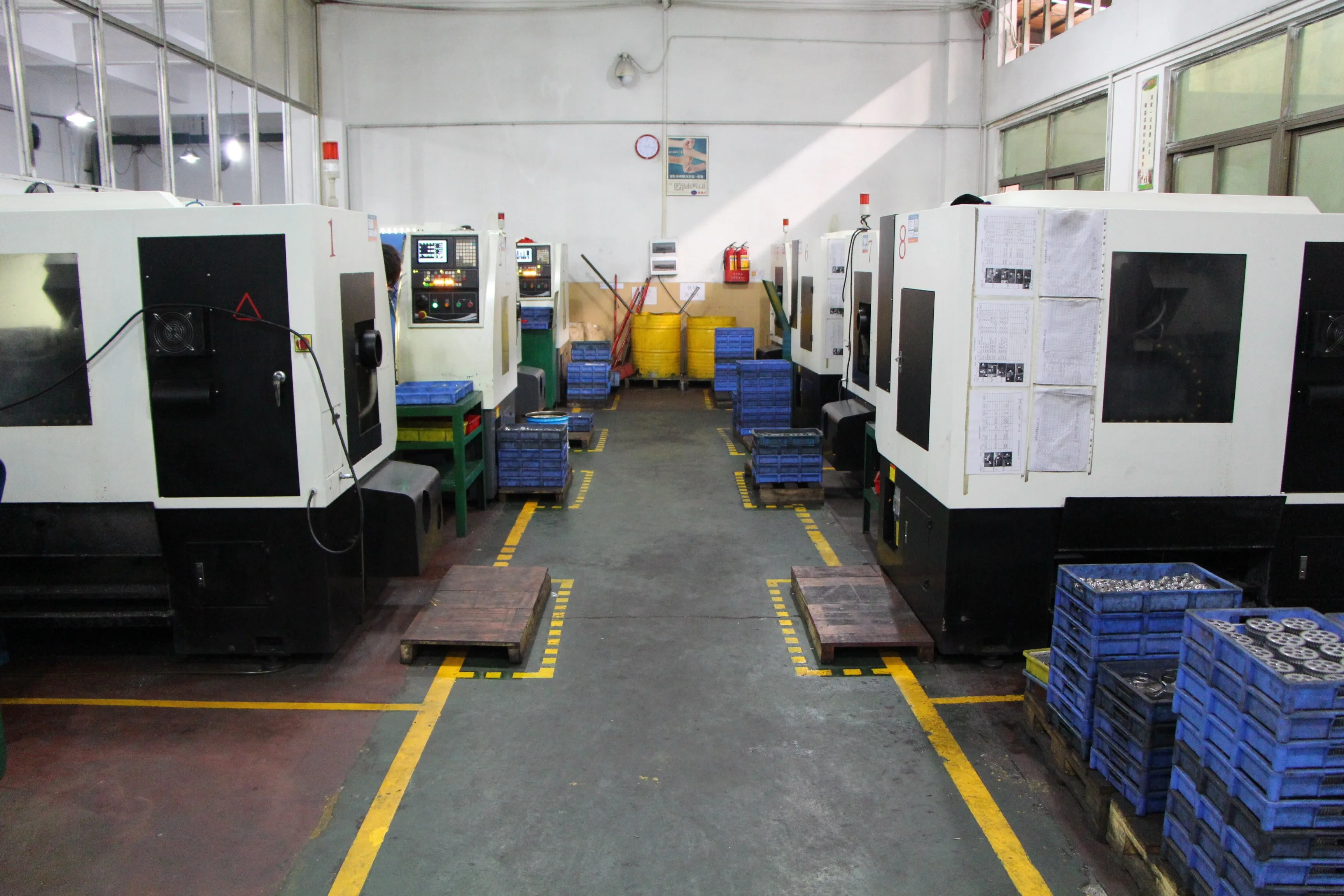
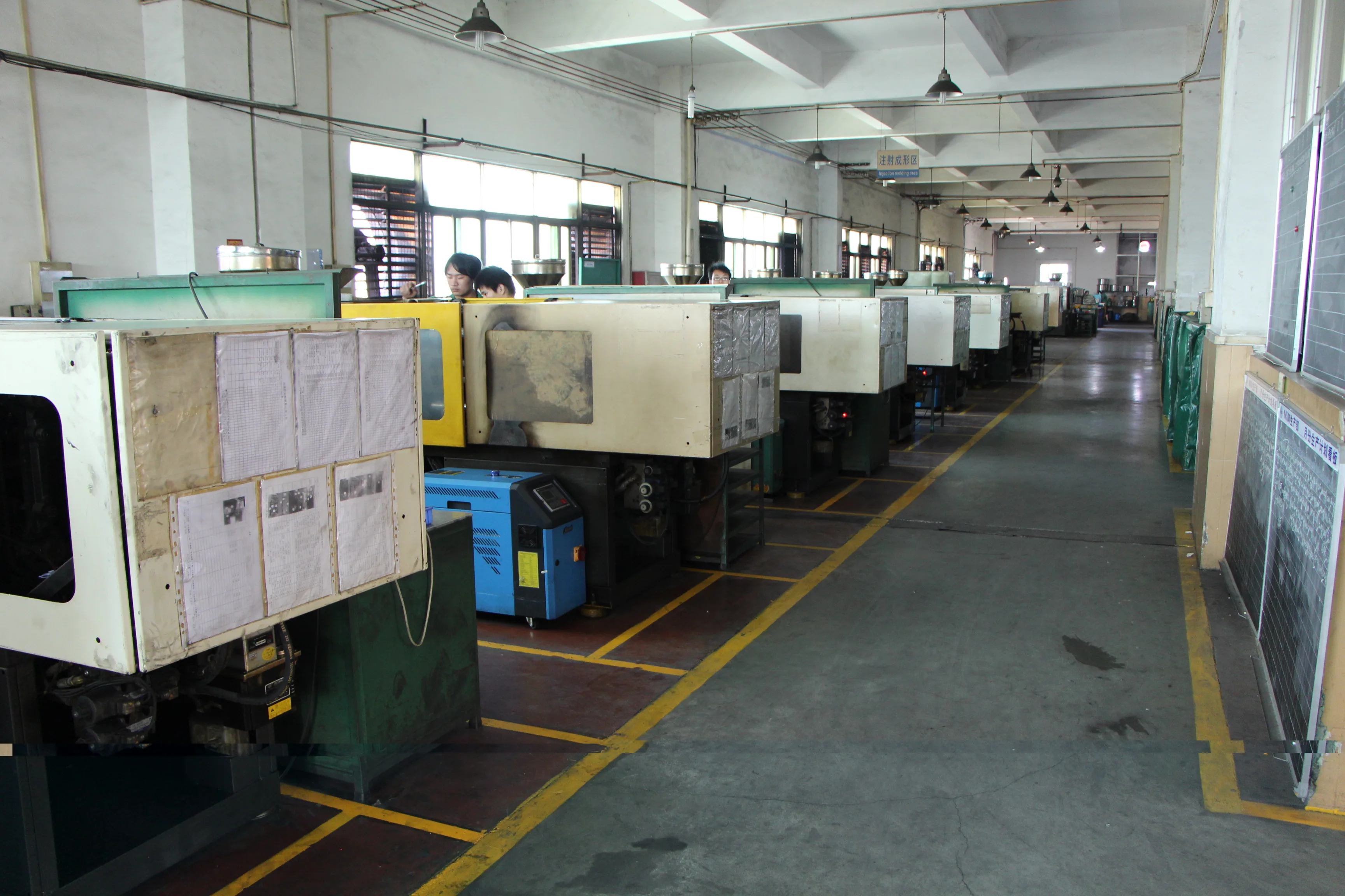
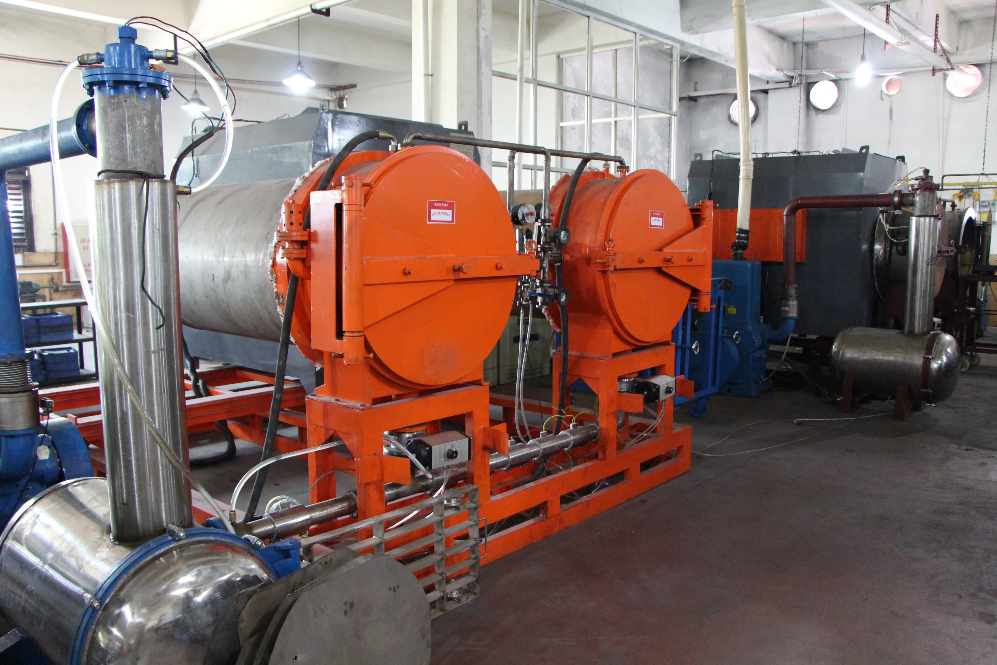
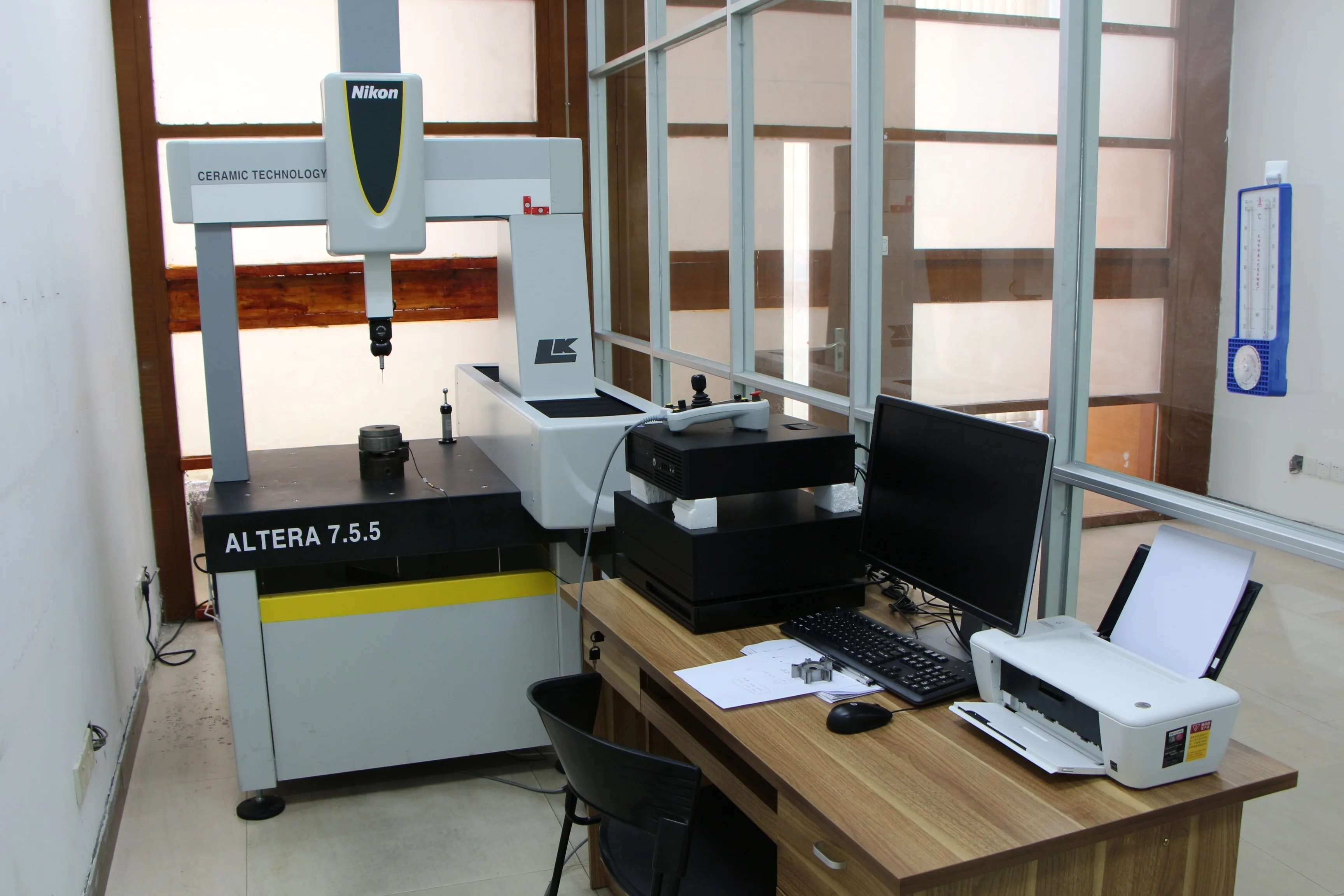
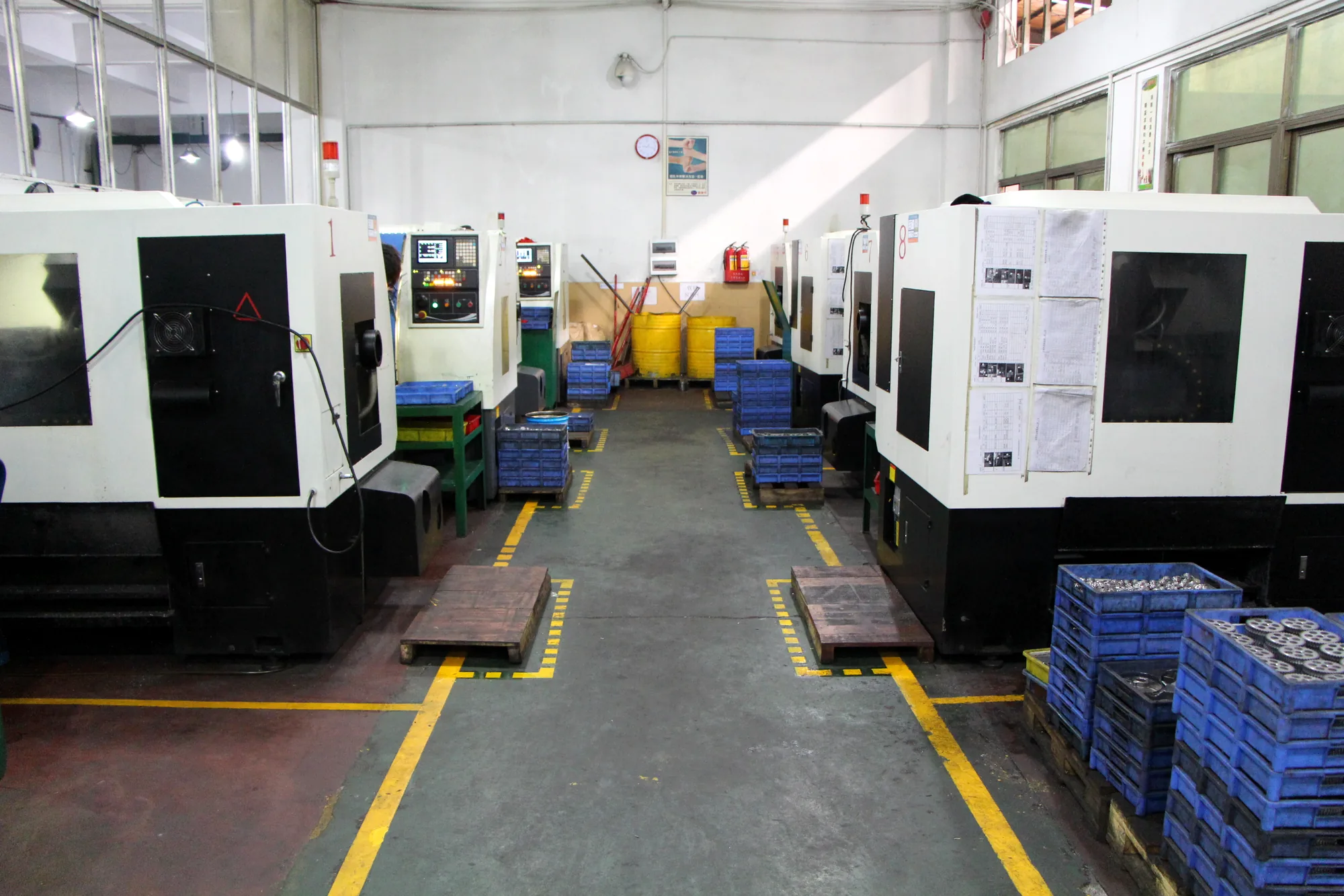
Real equipment, real parts, and manufacturing resources across Zhongshan and Jiangxi — with Zhongshan as the principal SINTS site for PM, MIM and inspection.
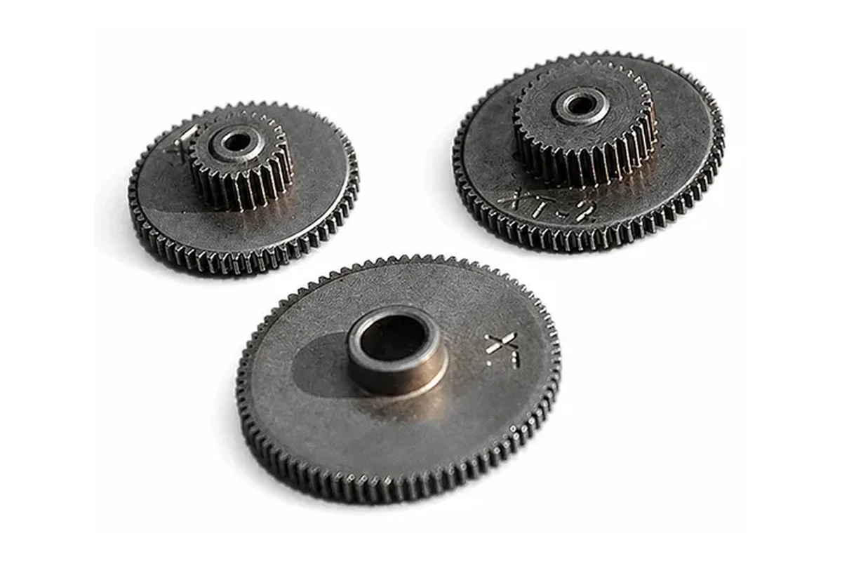
Representative custom geometry. Open the component review and define the requirements for your part.
Review this component →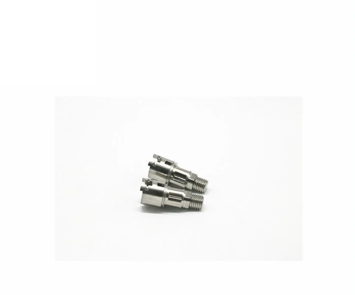
Representative custom geometry. Open the component review and define the requirements for your part.
Review this component →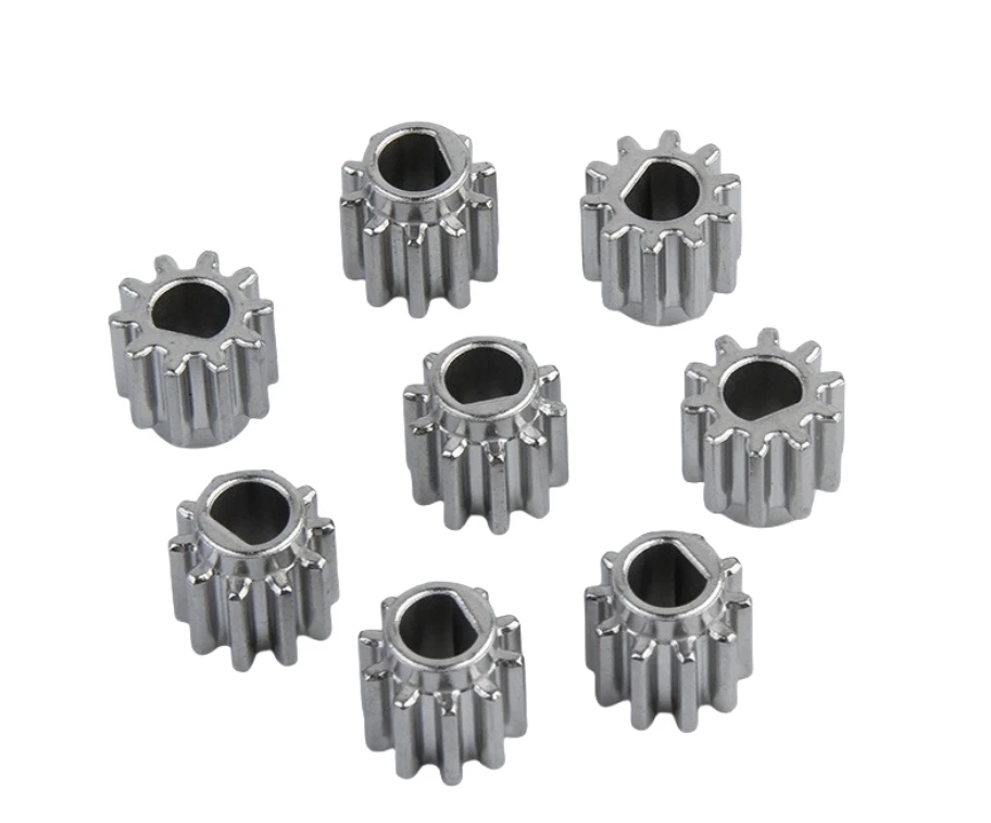
Representative custom geometry. Open the component review and define the requirements for your part.
Review this component →Three practical examples show where MIM or PM may help — and where critical dimensions, validation or low volume can keep CNC in the process plan.
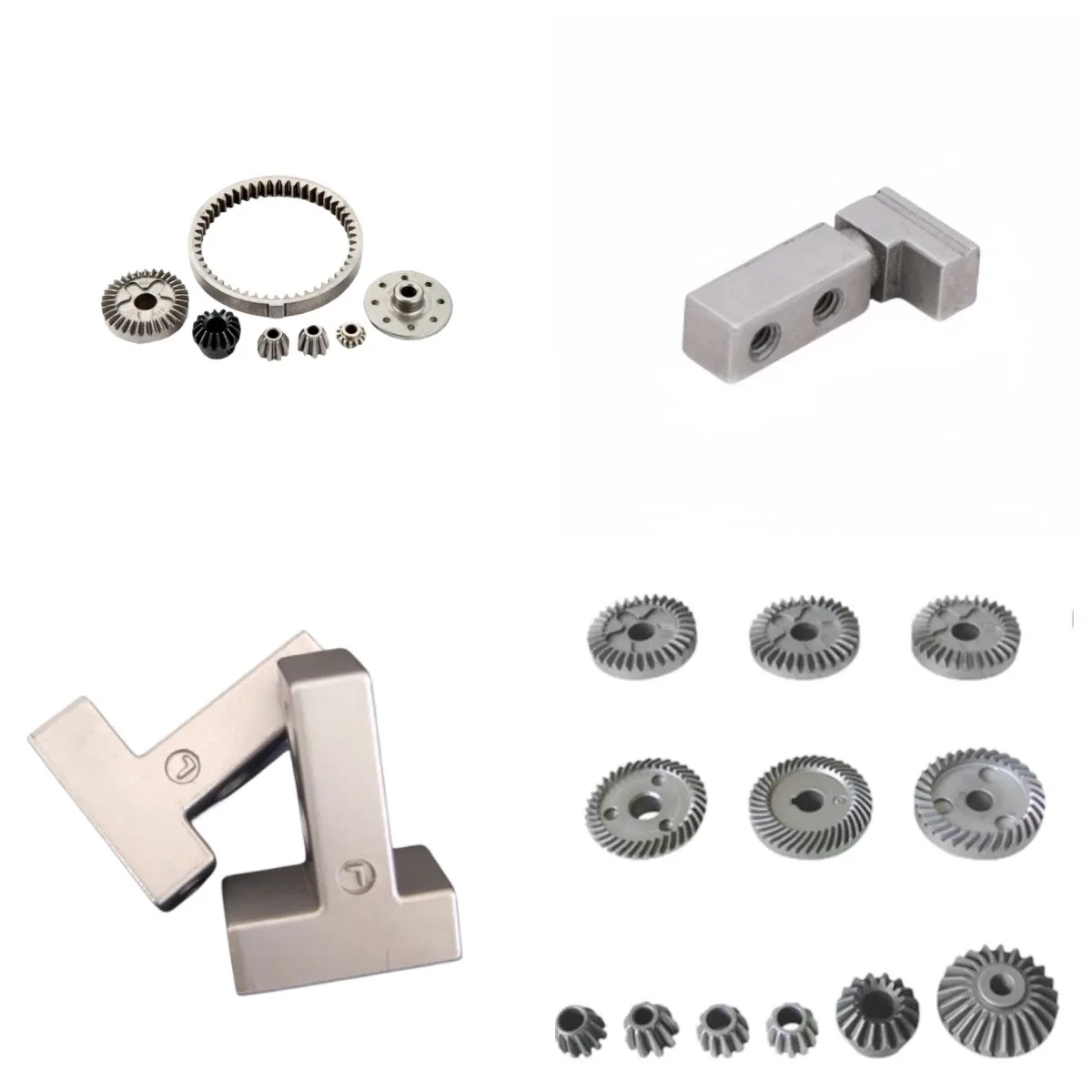
How complex profile, repeat volume and selective finishing can make a CNC-to-MIM evaluation worthwhile.
Read the case →
How serrations, undercuts, surface condition and inspection requirements affect a 316L MIM evaluation.
Read the case →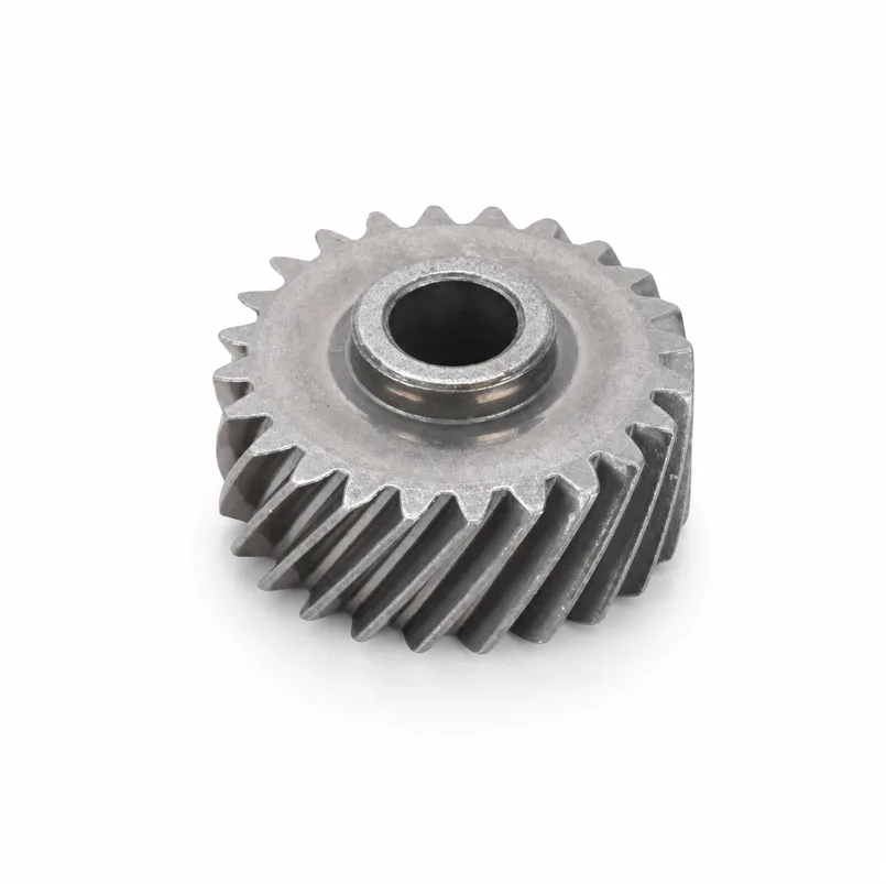
How density, tooth loading, hardness and secondary operations shape a PM gear process decision.
Read the case →Define gear geometry, mating interfaces, duty and final condition before comparing a drawing-based quotation.
Read the guide →PM & GearsReview which gear features need sizing, machining or heat treatment, and how the final inspection sequence should follow them.
Read the guide →Process SelectionCompare MIM and CNC using the same geometry, critical dimensions, material condition, volume and approval requirements.
Read the guide →Three practical questions to resolve before comparing unit prices or committing to tooling.
MIM may fit small, complex 3D metal parts when geometry consolidation and repeat volume justify tooling. Material, distortion risk, critical datums and secondary finishing still need drawing-level review.
Send a 2D drawing or 3D CAD file with material, annual volume, application, critical dimensions, finish, inspection requirements and target timing whenever available.
Yes. Dimensional reports, material confirmation, FAI, PPAP and other quality documentation can be planned when required by the drawing or customer program.
Each stage is defined by the drawing, tooling route and customer approval requirements rather than by a universal lead-time promise.
Send the drawing or CAD file with material, annual volume, application context and critical requirements.
Engineering reviews process fit, manufacturability, tooling assumptions, secondary operations and missing functional information.
Trial timing, dimensional inspection and customer-required approval documentation are confirmed with the project plan.
Repeat production follows the approved route, quality controls, packaging and shipment requirements agreed for the program.
Use this short form for an initial project review, or open the full RFQ page if you want to provide more material, tolerance, volume and process information.
Principal SINTS manufacturing site. ISO 9001 covers the Zhongshan quality management system; IATF 16949:2016 applies to the certified Zhongshan powder-metallurgy manufacturing scope.
In-person factory visits and project-specific remote review can be coordinated with the sales team.