
Product example
Power Tool Gear Components
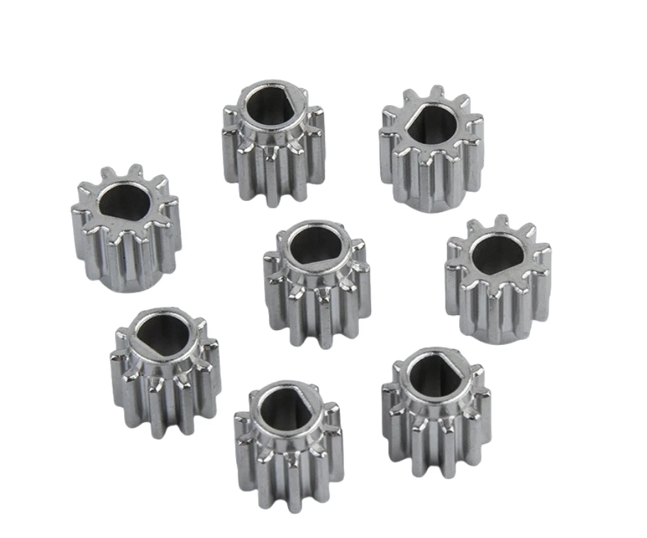
Small gear forms with different bore and hub details. Review their mating gear, load and installation requirements.
Power tool and industrial hardware components are the working parts inside tools and equipment — tool gears, pneumatic fork and clevis parts, guide and connecting components, connection bodies and wear hardware. SINTS produces these by powder metallurgy (PM), metal injection molding (MIM) or machining, with the route following the working duty and the surface that wears.
Small gear forms with different bore and hub details. Review their mating gear, load and installation requirements.
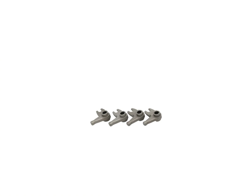
Forked mechanism parts with holes and contact features. Define pin fit, travel and load direction.
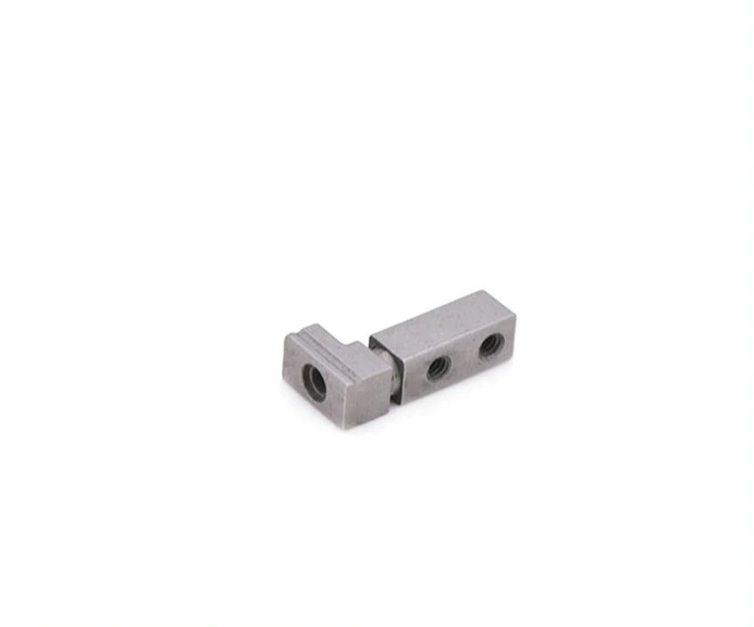
A stepped guide-related part with multiple openings. Clarify the locating, guiding and connecting surfaces.
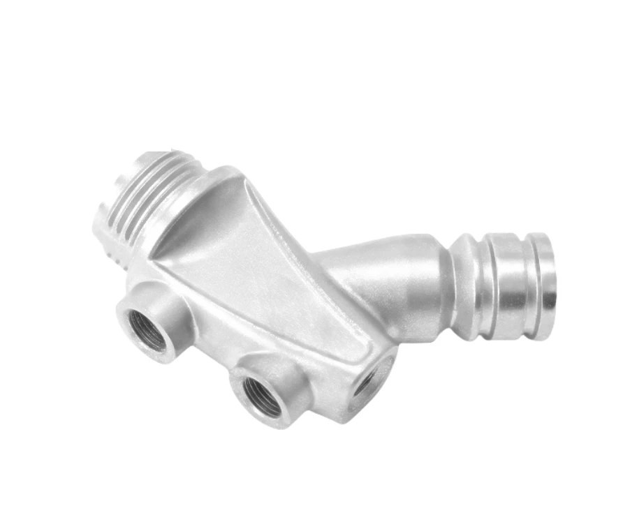
A body with intersecting connection features. Review openings, wall transitions and assembly datums on the part drawing.
Examples from the SINTS product catalog, shown for component identification. These are custom parts, not stock specifications. Dimensions, material, supply scope and acceptance requirements are confirmed from your project drawing.
Explore each component in detail, including its interfaces, manufacturing review and drawing requirements.
The fork examples show a compact component that transfers or guides motion. Supply the mating pin, load direction and movement range so the hole fit, fork ends and contact surfaces can be assessed as one assembly. Critical interfaces may need finishing after forming.
The gear examples illustrate a range of hub and bore shapes. For a new project, distinguish steady rotation from reversing or impact duty, and include the mating gear and installation datums. Material and final condition are confirmed against the agreed operating and inspection requirements.
The part drawing and its assembly determine the manufacturing route and the inspection plan.
Load direction, torque, impact, reversing and expected operating cycles.
Pin and shaft fits, travel, stops and contact geometry.
Material, heat treatment, wear surfaces and corrosion requirements.
Dimensional, assembly and agreed functional tests with mating parts.
Power tool and industrial hardware components are the working parts inside tools and equipment. These answers cover duty-based process selection, moving interfaces and sample qualification.
Repeat-volume gears and structural motion parts are the strongest candidates — spur and helical tool gears, drive and reduction parts, guide and connecting components, and bracket or body parts that carry a defined load. The decision then depends on duty, tooth loading, required density and whether a secondary machining operation is needed on a functional feature.
It changes which property matters. A continuously running drive is dimensioned for fatigue and wear, an intermittent high-load tool is dimensioned for peak stress and impact, and a tool that reverses or jams repeatedly accumulates damage that a steady-duty analysis would miss. Stating the duty cycle, peak load and any stall condition makes the material and treatment recommendation answer a real failure mode.
The pin and the moving interface. A fork or clevis transfers load through a pin or pivot, so the bore diameter and tolerance, the bearing surface, the alignment of the two arms and the hardness at the contact point determine whether the joint stays tight and whether the bore wears or elongates. Those are functional requirements rather than general dimensions.
A tool gear should be specified against the torque it actually transmits and the shock it sees, not against a nominal rating. Gear ratio, tooth form, density, hardness and backlash all follow from that, and where a gear is also a wear surface or a locating feature those functions need to be stated separately so they are addressed rather than assumed.
Sample approval compares the produced part against the agreed drawing and requirements using the intended assembly where relevant — fits, movement, surface condition and any agreed functional check. The acceptance criteria should be agreed before samples are made, so that the result of the check is a decision rather than a debate, and any first-article documentation is defined in the same step.
Include mating parts, operating load and motion, critical fits, final material condition and annual volume.