
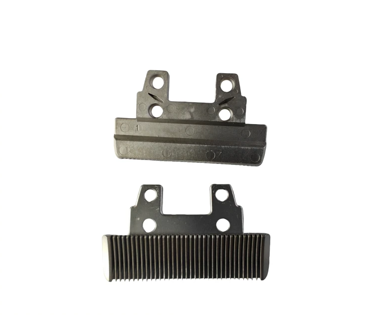
What clipper blades do in a defined cutting relationship
The catalog reference shows blade forms with mounting features whose alignment affects the working action.
Fixed and moving members, tooth geometry and stroke interfaces
Provide the fixed and moving members, tooth geometry, stroke and mounting arrangement.
Define the contact and clearance between the cutting members.
Why distinguish the fixed and moving cutting members?
Their relative position and movement define the cutting arrangement.
A tooth profile viewed alone does not describe that relationship.
Reviewing the pair helps connect individual blade manufacture with the required mounting, stroke and working-clearance checks.
Separating blank production from tooth and cutting-surface finishing
Review blank production separately from tooth and cutting-surface finishing.
Grinding or other finishing may be required regardless of how the body is formed.
Compare manufacturing capabilities →Blade material, wear treatment and operating-environment requirements
Define material and final treatment against load direction, wear and the operating environment.
Mark surfaces whose fit or contact changes after finishing.
Rated loads, pressure limits and operating life require their own agreed design and acceptance requirements.
Review material-selection information →Tooth condition, working clearance and cutting-test checks
Check tooth condition, mounting position, working clearance and the customer's functional cutting test.
Specify the required material and treatment condition.
Quality documentation →What moves between lots on a clipper blade pair
A clipper blade set cuts because two toothed members slide against each other under pressure. The cut depends on tooth form, edge condition and flatness, and the three change between lots in different ways.
| What drifts between lots | Where the drift comes from | What the release check catches |
|---|---|---|
| Tooth form and pitch | Teeth are formed and then ground on the cutting face. Grinding removes a fixed depth, so a blank that sinters slightly differently produces teeth that sit slightly differently after grinding. | Check tooth height, pitch and tip form on a finished part. Tooth geometry measured before grinding does not describe the cutting edge. |
| Flatness of the contact faces | The two members have to stay in contact across their width while sliding. Flatness is affected by sintering, by heat treatment and by how the face was ground. | Check flatness in the free state and check the fit of the pair under its spring load. A pair that is flat individually can still lift at one end when assembled. |
| Edge sharpness and its life | Sharpness comes from the last grinding step and from the hardness of the material. Two lots can meet the same dimensions and wear at different rates because edge geometry or hardness differs. | Agree a cutting test on a defined hair load and record results per lot. For a wear part, cutting performance over a test cycle is more useful than a single sharpness figure. |
| Hardness and case depth | Blades are hardened to resist wear. Position in the furnace and section thickness change the result, and the tips are thinner than the body. | Agree the test location at the tooth rather than on the body, and use coupons from the load. A body hardness reading can pass a set with soft teeth. |
| Clearance between the fixed and moving members | Clearance is set by the parts plus the spring. Each part can be in tolerance while the assembled clearance is outside the range that cuts well. | Check clearance on an assembled pair, and state which part carries the tolerance. This is what decides whether a set cuts or pulls. |
Agree on the sample size and inspection method before production.
A clipper set is accepted or rejected on how it cuts, and only the last two items come close to that. Tooth measurements and flatness readings are means; the cutting test and the assembled clearance are the end. A drawing that specifies the means without naming the end leaves the supplier to guess what the customer will judge.
What to include in your enquiry
- Drawing and mating dimensions.Provide the fixed and moving members, tooth geometry, stroke and mounting arrangement. Include the drawing revision.
- Mating information. Include the assembly references needed to define the interfaces discussed above.
- Delivered condition. State material, finishing and inspection requirements, identifying any items that need a manufacturing recommendation.
- Supply plan. Include sample needs, expected order and annual quantities, packaging requirements and target timing.
- First-sample inspection.Check tooth condition, mounting position, working clearance and the customer's functional cutting test. Specify the mating part or inspection fixture.
Common questions
Can a clipper blade be approved without its mating member?
Basic dimensions can be checked, but cutting clearance and movement require the intended mating blade and mounting.
Why distinguish the fixed and moving cutting members?
Their relative position and movement define the cutting arrangement. A tooth profile viewed alone does not describe that relationship. Reviewing the pair helps connect individual blade manufacture with the required mounting, stroke and working-clearance checks.
How should the part be checked in the tool or mechanism?
Check tooth condition, mounting position, working clearance and the customer's functional cutting test. Specify the required material and treatment condition.