
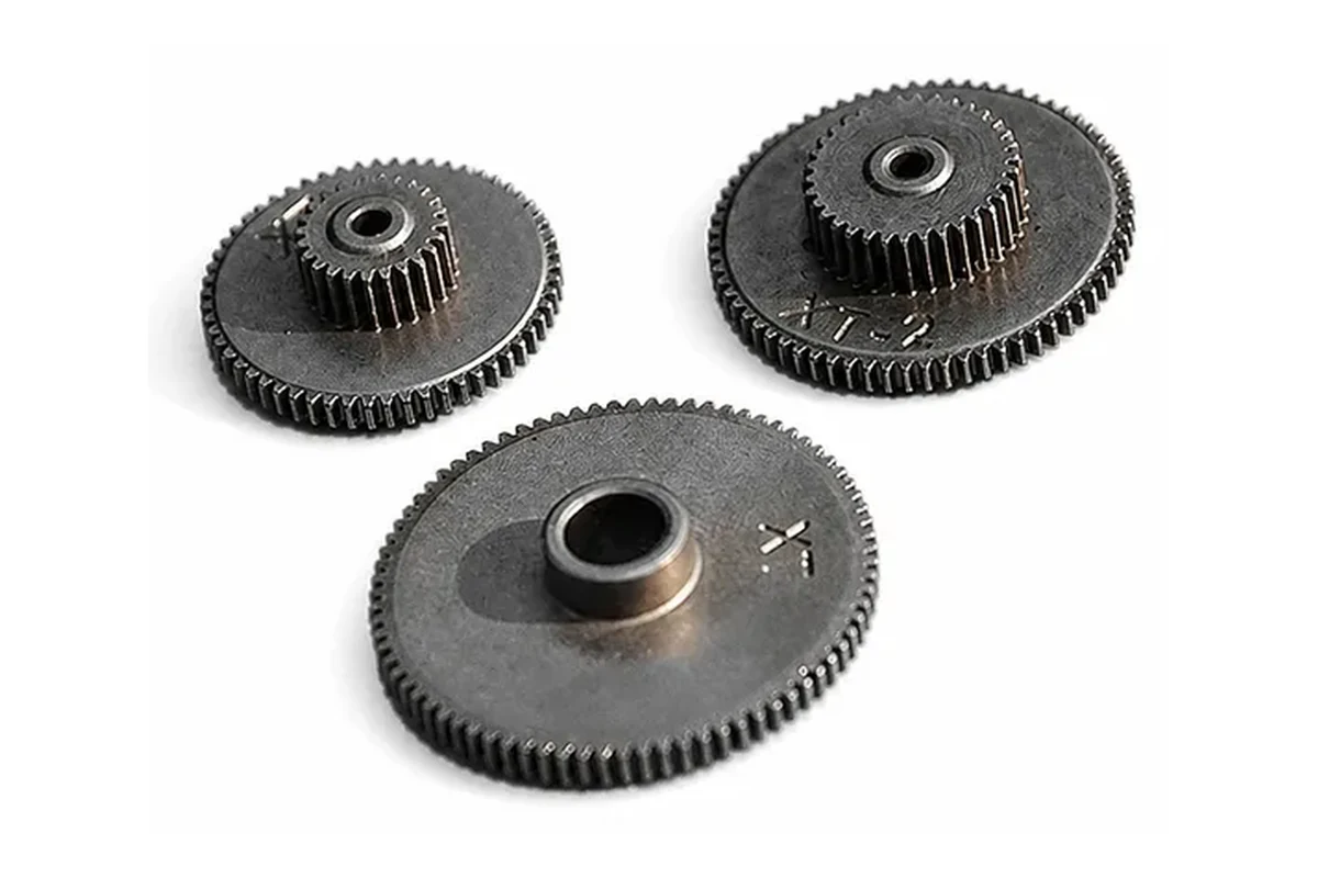
Product example
Spur Gears and Compound Gear Parts
Compound and hubbed gear examples. Tooth geometry and the mounting bore must be defined against consistent datums.
Gears and transmission components are the parts that transfer rotation and torque in a mechanism — spur, helical and bevel gears, compound gears, bushings and the mating supports around them. Powder metallurgy (PM) is usually the first route evaluated for these parts because it forms the tooth profile in one operation; metal injection molding (MIM) becomes relevant when the gear carries integrated geometry beyond the teeth.
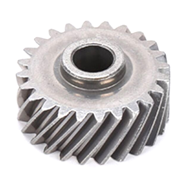
Compound and hubbed gear examples. Tooth geometry and the mounting bore must be defined against consistent datums.
An angled-tooth gear reference. Specify helix angle, hand, mating gear and parameter convention in the drawing.
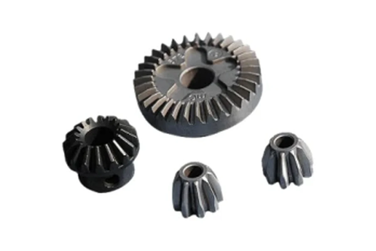
Angled-axis gear references. Review the mating pair, shaft angle and mounting position together.
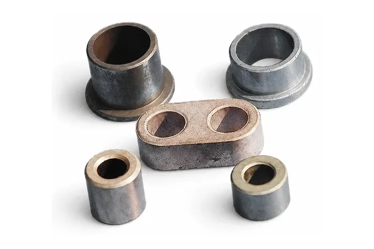
Plain and flanged bushing forms for supporting, locating or guiding a shaft. Fits and lubrication depend on the actual assembly.
Examples from the SINTS product catalog, shown for component identification. These are custom parts, not stock specifications. Dimensions, material, supply scope and acceptance requirements are confirmed from your project drawing.
Tooth count, module or pitch, pressure angle, face width and helix data.
Torque, speed, shock, lubrication and target life or acceptance test.
Bore fits, face datums, runout and the mating gear or shaft.
Material condition, sample quantity, annual demand and inspection scope.
Explore each component in detail, including its interfaces, manufacturing review and drawing requirements.
The examples include different tooth forms and integrated hubs. Tooth data alone is not enough to define a repeatable assembly: include bore fit, face datums, the mating gear and working load. The detailed guides below explain the information needed for each gear form.
The bushing examples show several external profiles. Define whether the part guides, locates or supports motion, then provide the mating shaft and housing. Lubrication and material condition should be specified for the duty rather than assumed from the photograph.
The part drawing and its assembly determine the manufacturing route and the inspection plan.
Tooth count, module or pitch, pressure angle, face width and helix data where applicable.
Bore fit, face datums, runout and mating component information.
Torque, speed, shock, noise, lubrication and duty cycle.
Agreed tooth, dimensional and assembly checks for sample approval.
Gears and transmission components transfer rotation and torque between shafts. These answers cover tooth geometry, mounting interfaces, backlash and how process route follows from the load case.
Spur, helical and planetary gears produced in repeat volume are the classic candidates, along with compound gears that combine a gear profile with a hub or boss, and bushings that support the same shaft. Suitability then depends on tooth loading, density, required accuracy, backlash and whether the gear needs a heat treatment or a machined bore afterwards.
Yes, and that is usually where MIM earns its place: a gear combined with a cam, a one-way feature, a splined hub or a lever arm that would otherwise need a second part or a second operation. When the geometry is essentially a gear and a bore, powder metallurgy is normally the better fit, and when it is essentially an axisymmetric hub, turning is.
Specify them as functional requirements tied to the meshing pair, not as one overall tolerance. Backlash, tooth-to-tooth variation, runout and center distance each affect noise and life differently, and a gear that meets a general dimensional tolerance can still run rough if backlash or tooth form drifts. Stating the mating gear and the acceptable noise or play gives the review something measurable to work against.
A significant one, because the gear's accuracy in the assembly depends on how it is located as much as on the teeth. Bore diameter and tolerance, concentricity between bore and pitch circle, keyway or spline features, hub length and face datum all determine whether the tooth geometry is actually used as designed. Machining or reaming of the bore after sintering is common for exactly this reason.
Peak load, fatigue duty, shock and lubrication should be reviewed together. Static tooth strength, fatigue at the tooth root, surface wear at the flank and any shock or reversing condition each point to different density, alloy and heat-treatment choices, and the same nominal gear can need a different treatment for a steady drive than for an intermittent one. Sharing stall and impact conditions makes the material recommendation meaningful.
Send complete tooth data, the mating gear, installation dimensions, working load, material condition and annual quantity.