
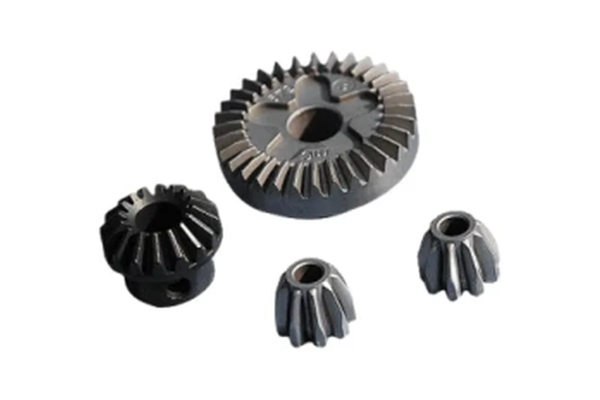
What bevel gears transmit between angled shafts
Review this component together with its mating parts and delivered condition. The interfaces below define the drawing information needed to assess forming, finishing and inspection.
The mating pair and its installation determine the useful tooth and mounting requirements.
Shaft angle, tooth data and mounting-distance interfaces
Provide shaft angle, tooth data, mounting distance and the mating gear drawing.
Bore and face datums need to relate to the designed tooth geometry.
Why does mounting distance belong in bevel-gear review?
The gear's working relationship is established by its position relative to the mating member.
Tooth geometry alone does not describe that installed position.
The assembly dimensions connect the individual gear to the intended contact and backlash requirements.
PM versus gear machining for bevel tooth forms
Compare PM and appropriate gear machining for the required tooth form, load and volume.
A near-net blank does not remove the need to define any tooth finishing or mounting-surface operations.
The proposed route is confirmed for your drawing, material and quantity. An image does not establish a fixed tolerance or a complete process specification.
Compare manufacturing capabilities →Gear material, density and treatment requirements
Material and final condition must be reviewed against the defined load, wear, lubrication and environment.
Where powder processing is proposed, agree any relevant density and treatment requirements.
A material family or hardness value alone does not specify the gear or bearing duty.
Review material-selection information →Gear geometry, mounting and backlash checks
Inspect gear geometry and mounting interfaces, then verify the agreed contact and backlash in the assembly.
Include the intended load and lubrication conditions.
Specify the drawing revision and the condition in which each dimension is inspected. Record the agreed dimensional and functional checks before sample approval.
Quality documentation →Prepare a Product-Specific RFQ
- Component definition. Send the 2D drawing and 3D model, where available, with the drawing revision and the requested part or assembly scope.
- Mating information. Include the assembly references needed to define the interfaces discussed above.
- Delivered condition. State material, finishing and inspection requirements, identifying any items that need a manufacturing recommendation.
- Supply plan. Include sample needs, expected order and annual quantities, packaging requirements and target timing.
Product Questions
Can one bevel gear be approved without its mounting position?
Dimensional checks are possible, but working engagement depends on the mating gear and installation geometry.
Why does mounting distance belong in bevel-gear review?
The gear's working relationship is established by its position relative to the mating member. Tooth geometry alone does not describe that installed position. The assembly dimensions connect the individual gear to the intended contact and backlash requirements.
Which checks should be included in gear or support approval?
Inspect gear geometry and mounting interfaces, then verify the agreed contact and backlash in the assembly. Include the intended load and lubrication conditions.
Technical Context
The product-specific notes above identify drawing-review questions. General process and material references are collected separately; they do not verify a material grade, production qualification or performance claim for the pictured part.
Manufacturing and material references →Bevel gear reference library
Component reference and drawing inputs
Bevel gear forms
Define the functional datums, mating interfaces and final condition for this part.
Discuss a similar component →Representative custom component references. Dimensions, material, manufacturing route and validation requirements are confirmed from your drawing; these are not off-the-shelf catalog items.