
Why a spider-gear request needs a defined transmission arrangement
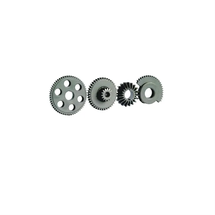
The available image is a general gear reference, not proof of a differential gear specification.
Assembly drawing, shaft arrangement and component-position interfaces
Provide the assembly drawing, shaft arrangement, mating teeth and component position.
Identify whether the requested item is a gear, carrier or another support in the mechanism.
Why use an assembly reference for an ambiguous gear name?
A catalog name may describe a function without defining the actual tooth or supporting geometry.
An assembly drawing resolves where the part sits and what it mates with.
Only then can the manufacturing comparison address the component actually required.
Choosing a route after tooth form and support geometry
Choose a route only after the tooth form and support geometry are resolved.
Compare gear machining or forming for the actual part rather than quoting from the catalog label.
Compare manufacturing capabilities →Spider gear material, density and treatment requirements
Material and final condition must be reviewed against the defined load, wear, lubrication and environment.
Where powder processing is proposed, agree any relevant density and treatment requirements.
A material family or hardness value alone does not specify the gear or bearing duty.
Review material-selection information →Tooth geometry, engagement and assembly-duty checks
Check the specified tooth and mounting geometry, engagement and assembly duty.
The acceptance plan should identify the mating components used in verification.
Quality documentation →Where spider and carrier gears fail: the tooth, the pin bore and the match
A spider gear works inside a set. It meshes with side gears, it rides on a cross pin, and it thrusts against a washer, so its failures are almost always failures of a pair or of a fit rather than of the gear alone. That is also why a single-part inspection report rarely predicts them.
| What goes wrong in service | What drives it | Where the drawing closes it out |
|---|---|---|
| Tooth scoring at low speed under load | Scoring is a lubrication and surface problem before it is a strength problem. If the flank finish and the hardness pairing with the side gear are not specified together, the softer surface transfers material and the pattern spreads. | Flank finish and hardness stated as a paired requirement with the mating gear identified, plus the lubricant condition; verified by a loaded run-in with a production mate and inspection of the contact pattern afterwards. |
| The cross-pin bore wears and eventually seizes | The bore carries the pin over a short length and often runs with marginal oil. Clearance and finish decide it, and pin deflection adds load at the bore edges. | Bore diameter, finish and the pin fit stated together, with the effective bearing length named; verified by a run-in test on the assembly followed by a bore measurement, since the wear only appears under load. |
| The set is noisy although every part measures in tolerance | Gears run as a set. If the parts are produced to individual limits and never matched or lapped as a set, the contact pattern spreads across the population and some sets whine. | Whether the set is matched, lapped or free-assembled, stated on the drawing as a requirement rather than left to convention; verified by testing sets, not parts, and recording the spread. |
| The thrust face wears into the washer | The face that runs against the washer sees sliding rather than rolling, and it is usually the least specified surface on the part. | Face flatness, finish and the treatment of the thrust face stated separately from the tooth flanks; verified by measuring end play after a loaded run. |
| Cracks appear between the pin windows | The material between window openings can be thinner than it looks on a section, and a compacted part loses density there. Cracks start at the window corner. | Minimum wall thickness between windows and corner radii called out, with a density requirement located at that web; verified by a load test to the intended torque and by sectioning a sample through the web. |
Use the project drawing for tolerances and acceptance limits.
The tooth and web items belong to tool design: root radius, window corners and local density are all fixed the moment the tool is cut, and no inspection plan recovers them. Bore wear and thrust-face wear are process and finish questions that a shop can hold. Noise is neither, and it is the item that most often turns into an argument, because it can only be resolved by deciding whether these gears are a set or a catalogue of interchangeable parts. That decision changes the price, so it is better made at quotation than at complaint.
What to include in your enquiry
- Drawing and mating dimensions.Provide the assembly drawing, shaft arrangement, mating teeth and component position. Include the drawing revision.
- Mating information. Include the assembly references needed to define the interfaces discussed above.
- Delivered condition. State material, finishing and inspection requirements, identifying any items that need a manufacturing recommendation.
- Supply plan. Include sample needs, expected order and annual quantities, packaging requirements and target timing.
- First-sample inspection.Check the specified tooth and mounting geometry, engagement and assembly duty. Specify the mating part or inspection fixture.
Common questions
Is the term spider gear enough to define the component?
No. Send the assembly position and full tooth or support geometry so that the intended part is unambiguous.
Why use an assembly reference for an ambiguous gear name?
A catalog name may describe a function without defining the actual tooth or supporting geometry. An assembly drawing resolves where the part sits and what it mates with. Only then can the manufacturing comparison address the component actually required.
Which checks should be included in gear or support approval?
Check the specified tooth and mounting geometry, engagement and assembly duty. The acceptance plan should identify the mating components used in verification.