
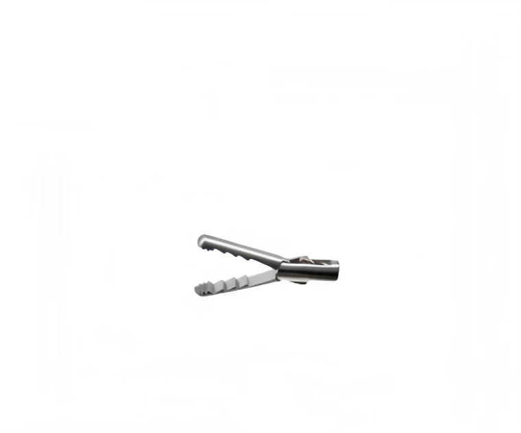
Product example
Grasping Forceps Jaw Components
A forceps assembly reference showing jaws and their connection. Identify the individual parts and alignment features required.
Medical device components are the metal parts inside surgical and diagnostic instruments — forceps jaws, tweezer and clip parts, instrument handles and the alignment and edge features that make them work. SINTS produces these by metal injection molding (MIM), powder metallurgy (PM) or machining. For implant and patient-contacting applications, project-specific material, verification and regulatory review is required.
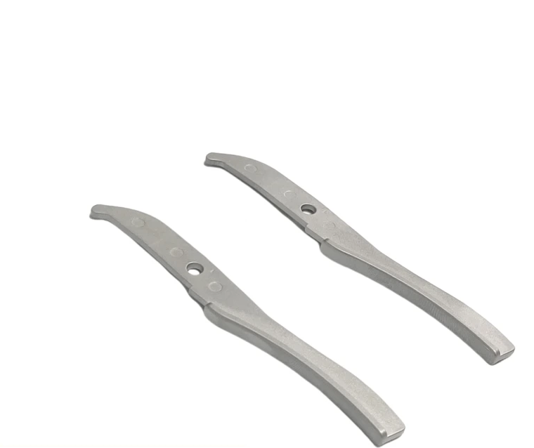
A forceps assembly reference showing jaws and their connection. Identify the individual parts and alignment features required.
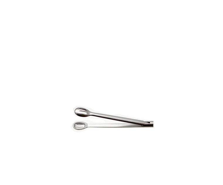
A tweezer-style instrument example. Define component scope, contact surfaces, alignment and finishing requirements.
Paired slender handle forms with holes and curved profiles. Mating position, edge condition and functional surfaces need drawing-level definition.
Examples from the SINTS product catalog, shown for component identification. These are custom parts, not stock specifications. Dimensions, material, supply scope and acceptance requirements are confirmed from your project drawing.
Explore each component in detail, including its interfaces, manufacturing review and drawing requirements.
The paired handle examples show why a component drawing should be read with its mating instrument. Mark pivot or connection holes, contact surfaces and the required edge condition. Agree dimensional inspection and sample assembly checks before confirming the manufacturing route.
An assembly photograph helps explain the jaw and connection arrangement. For a quotation, identify the individual metal parts to be supplied and provide their drawings. Material, final surface condition, cleaning and traceability requirements must be defined by the project.
The part drawing and its assembly determine the manufacturing route and the inspection plan.
Individual part drawings, mating instrument and intended component function.
Hole positions, jaw or handle alignment, contact faces and edge condition.
Roughness, finishing, cleaning and handling requirements specified by the customer.
Material records, traceability, inspection and project-specific validation requirements.
Three reference tables for instrument and device parts: the grades used in practice, where the forming routes stop, and what has to be agreed before tooling starts.
| Grade | Condition | Yield / UTS (MPa) | Elong. | Hardness | Density (g/cm³) | Why it is used here |
|---|---|---|---|---|---|---|
| 316L | Sintered | 250 / 498 | 40% | 110–160 HV | 7.75 | Handles, frames and implant-adjacent hardware. Corrosion resistance first, and the elongation to survive bending and drop without cracking. |
| 17-4PH | Sintered → aged | 720 / 900 → 1070 / 1160 | 11% → 7% | 20–25 → 35–45 HRC | 7.50 | Jaws, shafts and ratchet parts that need strength plus a surface that accepts a fine finish. |
| 420 | Heat treated | 1150 / 1310 | 6% | 40–45 HRC | 7.40 | Cutting edges and scissors: the hardness band that holds an edge without turning brittle. |
| 440C | Sintered | 1550 / 1750 | 1% | 58–62 HRC | 7.50 | Wear parts and bearing surfaces where edge retention outranks toughness. |
| Ti-6Al-4V (TC4) | Sintered | 950 / ≤1764 | 10–15% | 30–36 HRC | 4.50 | Weight-critical and implant-relevant work. Feedstock runs roughly five to ten times the stainless cost, so it is specified only when mass or biocompatibility decides. |
Values are reference ranges from the SINTS material summary, not design allowables for an implant. Titanium in particular needs its oxygen and interstitial limits agreed from the specification before the route is fixed — density alone does not qualify the material.
| Requirement | Powder compaction | MIM | What it means here |
|---|---|---|---|
| As-sintered tolerance, general dimensions | Roughly ±0.3–0.5% of the dimension | Roughly ±0.3–0.5% of the dimension | A 3 mm pivot hole and a 30 mm shank built to the same percentage carry very different absolute tolerance |
| Features tighter than about ±0.05 mm | Sizing or machining | Machining after sintering | Pivot bores and cutting edges are finished, not formed |
| Edge radius and burr condition | Requires a defined finishing operation | Requires a defined finishing operation | A cutting edge is a finishing specification, not a forming one — it has to be written on the drawing |
| Surface condition and cleanliness | Passivation and cleaning must be specified | Same — and finer moulded surfaces reduce, but do not remove, the need for it | “Clean” has to be defined: residue limits, particle limits, packaging and shelf life |
| Documentation | Material certificate, dimensional report, hardness and density | Same | The inspection plan is agreed before tooling, not after the first samples arrive |
These are manufacturing limits, not regulatory ones. Whether a component is suitable for a given device classification is decided by the device manufacturer’s own quality system; SINTS supports the part-level evidence — material, dimensions, hardness, density and microstructure — that this evidence feeds.
| Stage | Typical lead time | What you receive | What we need from you |
|---|---|---|---|
| Drawing review and DFM feedback | Issued with the quotation | Feature-by-feature route proposal, tolerance and finishing notes, and the open points that must be answered before tooling | 2D drawing with tolerances and datums, STEP model, target annual volume, material or the performance requirement |
| Tooling | 25–30 days as quoted on recent programs | Mould or die built and released to trial condition | Approval of the DFM report and confirmation of the alloy |
| T0 samples | 7–10 days after tooling release as quoted on recent programs | Parts plus a dimensional report against the drawing | Agreed inspection plan and datum scheme |
| Sizing, finishing and heat treatment | Runs inside or immediately after the sample stage | Sized and finished parts, hardness and density results where specified | Which features must be held after sintering, and which may be finished |
| First-article report | With the first approved samples | Dimensions, material, hardness and density measured in-house rather than subcontracted | Drawing with the critical characteristics marked |
| Production release | After sample approval | Serial production to the agreed inspection plan | Confirmed annual volume, MOQ and packaging |
Tooling and sample durations above are the lead times quoted on recent programs of comparable size, not a standard promise; the schedule for a specific part is confirmed with its quotation. Every result in the first-article report is measured on the instruments listed on the capabilities page.
Medical device components are the metal parts inside surgical and diagnostic instruments. These answers cover process selection, edge and surface requirements, documentation and the boundaries of a manufacturing review.
It covers the metal parts that make an instrument function — grasping jaws and tips, tweezer and clip components, instrument handles and their alignment features, linkages and the retention hardware around them. These parts are typically small, produced in repeat volume and judged on functional geometry, surface condition and documentation, so the review scope is narrower than for a device as a whole.
It can be evaluated where the geometry is genuinely three-dimensional — integrated hinge details, formed gripper profiles, combined handle and jaw features — and where volume justifies tooling. The functional geometry, the edge condition at the tip and the final surface then become explicit requirements, and any operation needed to achieve them is planned as part of the route rather than added later.
Define exactly which metal component is being quoted, separately from the finished instrument. A photograph of an assembled instrument is context, not a supply scope, and clarifying whether the scope is a raw component, a component with secondary operations, or a sub-assembly prevents a mismatch between what is quoted and what is expected.
Material and process documentation can be prepared for the manufacturing scope and agreed during supplier qualification, including material declarations and inspection records for the quoted part. What cannot be supported is a claim that a component is suitable for a specific clinical or patient-contacting use: implant-grade, sterility-compatible or regulatory claims require project-specific material selection, verification and regulatory review and are not asserted here.
Send the part drawing, the component's function in the instrument, the critical geometry and edge requirements, the required surface condition, the material and any cleaning or sterilisation exposure, the documentation the program needs and the annual volume. Those inputs let the review address manufacturability and documentation without overstepping into clinical or regulatory conclusions.
Send the component and assembly drawings, material specification, finishing, documentation and sample acceptance requirements.