
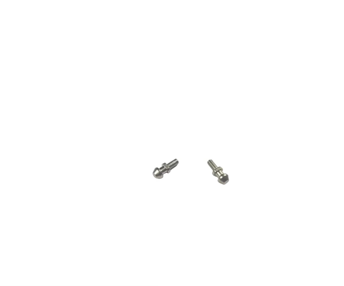
What a syringe mechanism head connects between members
Review this component together with its mating parts and delivered condition. The interfaces below define the drawing information needed to assess forming, finishing and inspection.
The individual part and its function must be identified from the assembly.
Head profile, stem connection and mating-surface interfaces
Define the head profile, stem or connection and the mating surface.
State whether the component is inside or outside any fluid-contact path.
Why identify the head component's position in the mechanism?
Its location determines whether it locates, connects or transmits movement and whether any surface has a specified contact role.
That information is not visible from a small loose part alone.
The assembly provides the basis for appropriate manufacturing and inspection requirements.
Machining versus MIM at the syringe-head scale
Compare machining and MIM for the scale and integrated features.
Small connection dimensions and edge condition need suitable inspection access.
The proposed route is confirmed for your drawing, material and quantity. An image does not establish a fixed tolerance or a complete process specification.
Compare manufacturing capabilities →Syringe head material, surface and traceability requirements
Provide the material specification, final surface requirements and documentation needed for the component.
Cleaning, traceability and device-related validation must follow the customer project.
The catalog reference does not establish medical compliance or an intended clinical use.
Review material-selection information →Head geometry, movement and material-documentation checks
Check head and connection geometry, movement and material documentation.
Specify cleaning, contact and device requirements only as they apply to the actual part.
Specify the drawing revision and the condition in which each dimension is inspected. Record the agreed dimensional and functional checks before sample approval.
Quality documentation →Where syringe mechanism heads fail, and why the seal, not the geometry, decides
A plunger head has one job in service and another in validation. In service it has to move smoothly and not leak; in validation it has to be provably clean. Most of the failures below sit at the point where those two requirements meet the tolerances of the barrel it runs in.
| What goes wrong in service | What drives it | Where the drawing closes it out |
|---|---|---|
| Fluid passes the head under pressure | Sealing depends on the head outside diameter against the barrel bore, and on roundness rather than on average size. A head that measures on the mean but is slightly oval will seal on two sides and leak on the other two. | Diameter and roundness stated separately, plus concentricity of the head to the stem, with the barrel bore range named; verified by a leak test at the specified pressure on assembled units, which is the only place the pairing exists. |
| Travel is jerky at low speed | Surface finish on the head outside diameter and the condition of the running surface decide stiction. A finish that looks fine under general lighting can still be rough enough to hold the head and release it in steps. | A finish requirement stated numerically on the sealing surface only, with the measurement direction named; verified by a slow-speed force trace on assembled units rather than by a roughness reading on a coupon. |
| The head separates from the stem | The junction between head and stem is a section change carrying the full actuation force, and it is usually the smallest radius on the part. | Junction radius and minimum neck section stated, with the actuation force the joint must survive; verified by a push-to-failure test with the load applied as it is in the barrel. |
| Particulate is found in the fluid path | Burrs at the stem junction and at any cross-hole are the usual source, and they are created by the last machining step rather than by the forming step. | A burr-free requirement on fluid-contact features with the inspection magnification named, plus a cleaning and packing condition; verified by a particle count on cleaned parts, not by visual check. |
| Dose accuracy drifts after sterilization | Thermal cycling moves dimensions, and if the head and the barrel are different materials they move by different amounts. The dose error appears only after the units have been through the cycle. | The fit specified in the post-sterilization condition with the barrel material named, and the sterilization cycle stated; verified by measuring dose delivery on units that have been through the cycle rather than on fresh assemblies. |
Note. The table names service failure modes and the drawing features that address them; it sets no acceptance values. Dimensions, tolerances and test criteria come from the project drawing.
The sealing items are pairing problems and can only be settled with the barrel in hand, which is why they belong in the RFQ rather than in a component specification. The junction strength and the burr condition are things a shop controls directly. The sterilization item is the one most often missed, because it is a validation question dressed as a tolerance question: a fit that is right at 20 degrees and wrong after an autoclave cycle is not a manufacturing defect, it is a specification that was written in the wrong condition.
Prepare a Product-Specific RFQ
- Component definition. Send the 2D drawing and 3D model, where available, with the drawing revision and the requested part or assembly scope.
- Mating information. Include the assembly references needed to define the interfaces discussed above.
- Delivered condition. State material, finishing and inspection requirements, identifying any items that need a manufacturing recommendation.
- Supply plan. Include sample needs, expected order and annual quantities, packaging requirements and target timing.
Product Questions
Should this component be assumed to contact the injected fluid?
No. Its position and function in the customer assembly determine the applicable contact and cleaning requirements.
Why identify the head component's position in the mechanism?
Its location determines whether it locates, connects or transmits movement and whether any surface has a specified contact role. That information is not visible from a small loose part alone. The assembly provides the basis for appropriate manufacturing and inspection requirements.
What must the sample approval requirements define?
Check head and connection geometry, movement and material documentation. Specify cleaning, contact and device requirements only as they apply to the actual part.
Technical Context
The product-specific notes above identify drawing-review questions. General process and material references are collected separately; they do not verify a material grade, production qualification or performance claim for the pictured part.
Manufacturing and material references →