
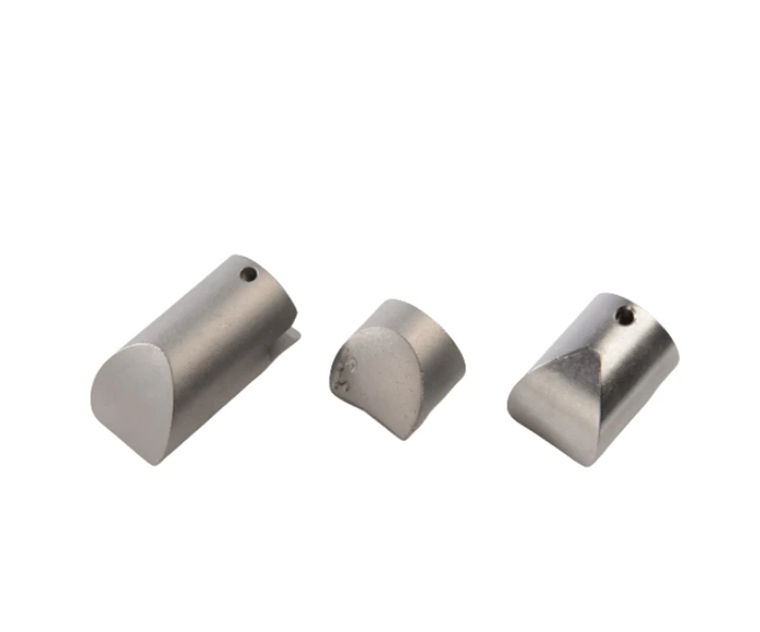
What sintered deadbolt forms need from guides and engaging surfaces
The catalog shows multiple profiles for drawing-based review.
Guide geometry, working stroke and connecting-feature interfaces
Provide the guide geometry, working stroke and connecting features.
Relate the engaging face to the datums that locate the bolt.
Why distinguish guide surfaces from the engaging face?
The guides position the bolt, while the engaging face interacts with the mating lock member.
Both are functional but serve different roles.
Their required relationship should be explicit so inspection can confirm the delivered part's intended fit and action.
Powder forming versus machining against pressing access
Compare suitable powder forming and machining based on section and pressing or molding access.
Finished guide surfaces may require separate operations.
Compare manufacturing capabilities →Sintered deadbolt material, treated-surface and corrosion requirements
Specify the base material, final condition and corrosion or appearance requirements.
Mark drive, guiding and contact surfaces that must meet their dimensions after treatment.
Specify any testing required on the assembled lock separately.
Review material-selection information →Body fit, end engagement and installed-clearance checks
Check body fit, end engagement and clearance in the installed position.
Specify final surface condition and the agreed mechanism test.
Quality documentation →Deadbolt bodies: density, section change and the shear face
A deadbolt is a load path with a shape problem. The section changes along the throw, the shear face has to stay flat and square, and a guide rib has to keep the bolt from rotating in the case. Sintering treats those three requirements very differently, so they need to be reviewed separately.
| Feature | What it governs | How it is specified and verified |
|---|---|---|
| Section change along the throw | Density gradient through the body, and the distortion that follows from it. | Wall transition radius and section ratio stated on the drawing; density measured on a cut sample at the thin and thick ends. |
| Shear face integrity | How the load leaves the bolt and enters the case, and whether porosity sits on that plane. | Face flatness and squareness to the throw axis; a porosity acceptance level agreed for the shear plane specifically. |
| Throw length and stop face | Whether the bolt reaches full engagement and stops where the mechanism expects. | Throw dimension and stop-face position; functional check inside the lock body, since a loose part cannot show the stop. |
| Guide rib or anti-rotation feature | Whether the bolt stays on axis under load instead of turning in the case. | Rib width and engagement depth; go/no-go against the mating case feature. |
| Plating over a sintered surface | Appearance and adhesion, which depend on whether open porosity has been closed first. | Sealing step stated before plating where required; adhesion check by the agreed method, on the finished part. |
Use the dimensions and acceptance criteria on the project drawing.
If the bolt is a uniform bar with no rib and no pocket, pressing and sintering a compact is simpler and cheaper than moulding. The case for MIM only appears once the geometry carries undercuts, a stepped throw or an integrated guide. Where the shear face must hold a high load in a thick section, a wrought or forged blank should be priced alongside before the route is committed.
What to include in your enquiry
- Drawing and mating dimensions.Provide the guide geometry, working stroke and connecting features. Include the drawing revision.
- Mating information. Include the assembly references needed to define the interfaces discussed above.
- Delivered condition. State material, finishing and inspection requirements, identifying any items that need a manufacturing recommendation.
- Supply plan. Include sample needs, expected order and annual quantities, packaging requirements and target timing.
- First-sample inspection.Check body fit, end engagement and clearance in the installed position. Specify the mating part or inspection fixture.
Common questions
Can different deadbolt profiles share the same lock-body guide?
Only if the required geometry and clearances match; verify the mating guide rather than comparing general appearance.
Why distinguish guide surfaces from the engaging face?
The guides position the bolt, while the engaging face interacts with the mating lock member. Both are functional but serve different roles. Their required relationship should be explicit so inspection can confirm the delivered part's intended fit and action.
How should the completed mechanism be checked?
Check body fit, end engagement and clearance in the installed position. Specify final surface condition and the agreed mechanism test.