
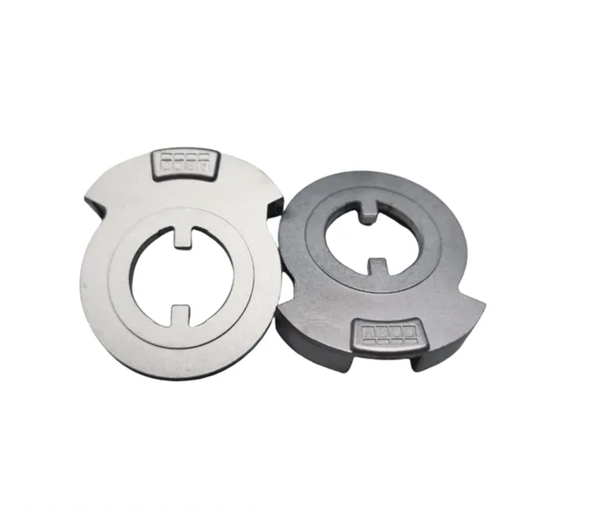
What combination-lock discs coordinate through openings and profiles
Review this component together with its mating parts and delivered condition. The interfaces below define the drawing information needed to assess forming, finishing and inspection.
Similar outlines can have different indexing requirements.
Stack arrangement, central drive and angular-position interfaces
Provide the stack arrangement, central drive and relative angular positions.
Distinguish contact or indexing edges from clearance regions.
Why include the stack arrangement of lock discs?
Disc thickness, orientation and working openings act together in the assembled mechanism.
An individual disc can meet its own dimensions without establishing the full sequence.
The stack arrangement identifies the relationships that must be verified across the parts.
PM, MIM and machining for disc profiles
Compare PM, MIM and machining for the disc profile and any integrated features.
Critical thickness and working profiles may need dedicated finishing or inspection.
The proposed route is confirmed for your drawing, material and quantity. An image does not establish a fixed tolerance or a complete process specification.
Compare manufacturing capabilities →Disc stacks: which process holds the indexing
A combination lock fails from accumulated angular error between discs, not from any single disc being out of tolerance. That changes the comparison: the question is not which process makes a disc accurately, it is which process makes a stack that stays accurate.
| Alternative process | When it wins on this part | What puts sintering back in front |
|---|---|---|
| Fine blanking | Wins on the flat disc with uniform thickness. The sheared edge comes off the tool clean and square, which is exactly the surface the indexing edge needs. | Fine blanking produces one outline and one thickness. A step, an integral hub, or a shoulder on the same disc needs a second part or a second operation, and the assembly tolerance then lands on the indexing edge. |
| Conventional stamping | Wins on spacers and non-functional washers in the same stack, where nothing indexes against the edge. | Burr height and flatness are uncontrolled, and both feed straight into stack height and angular position. Mixing stamped and formed discs in one stack is where the error budget is usually lost. |
| Wire EDM or laser cutting | Wins at prototype, and wins whenever several angular variants are being evaluated, because a new angle only needs a new program. | The cut face carries a recast layer and a taper that varies with thickness. Once one variant is chosen and the volume is known, a forming tool makes the same edge without either. |
| Zinc die casting | Wins on the housing and the outer sleeve that surrounds the stack, where the wall is heavy and the tolerance is generous. | It does not compete for the thin disc itself. A cast disc thick enough to fill is too thick for the stack height the mechanism was designed around. |
| Sintering | Wins where a hub, a shoulder and the disc outline belong to one part, so the angular relationship is set by the tool instead of by an assembly. | It loses on a plain disc. There, fine blanking is cheaper and its edge is better suited to indexing than a sintered face that has to be sized afterwards. |
Note. This table is a screening aid, not a recommendation against our own process. Where a row above describes your part better than the sintering route does, we will say so and quote against the route that actually fits; the quantities, alloy and tolerances on your drawing still decide the answer.
The drawing decision that matters more than the route: whether the angle is toleranced on the single disc or on the assembled stack. Tolerancing each disc looks tighter and is weaker, because the errors add. Tolerancing the stack matches how the lock actually fails, and no process can inspect its way out of the wrong choice.
Disc and ring material, treated-surface and corrosion requirements
Specify the base material, final condition and corrosion or appearance requirements.
Mark drive, guiding and contact surfaces that must meet their dimensions after treatment.
The component specification does not establish a security rating for the complete lock.
Review material-selection information →Thickness, angular relationship and stack-movement checks
Check thickness, angular relationships and movement within the intended stack.
Define the engagement sequence and acceptable clearances.
Specify the drawing revision and the condition in which each dimension is inspected. Record the agreed dimensional and functional checks before sample approval.
Quality documentation →Prepare a Product-Specific RFQ
- Component definition. Send the 2D drawing and 3D model, where available, with the drawing revision and the requested part or assembly scope.
- Mating information. Include the assembly references needed to define the interfaces discussed above.
- Delivered condition. State material, finishing and inspection requirements, identifying any items that need a manufacturing recommendation.
- Supply plan. Include sample needs, expected order and annual quantities, packaging requirements and target timing.
Product Questions
Can combination-lock discs be approved individually only?
Individual measurements are needed, but stack fit and the required sequence should also be checked with the mating components.
Why include the stack arrangement of lock discs?
Disc thickness, orientation and working openings act together in the assembled mechanism. An individual disc can meet its own dimensions without establishing the full sequence. The stack arrangement identifies the relationships that must be verified across the parts.
How should the completed mechanism be checked?
Check thickness, angular relationships and movement within the intended stack. Define the engagement sequence and acceptable clearances.
Technical Context
The product-specific notes above identify drawing-review questions. General process and material references are collected separately; they do not verify a material grade, production qualification or performance claim for the pictured part.
Manufacturing and material references →