
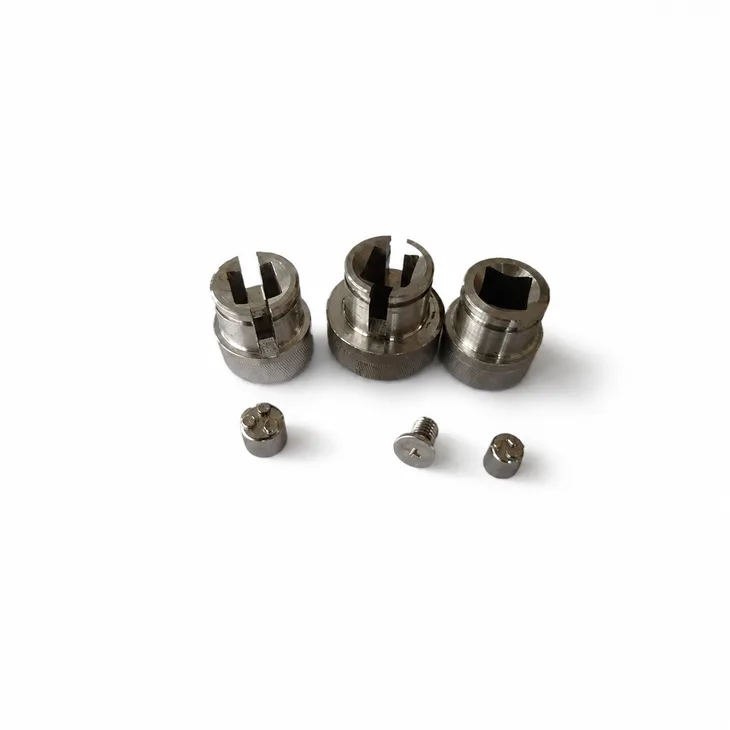
What a drive insert transmits through a shaped connection
Review this component together with its mating parts and delivered condition. The interfaces below define the drawing information needed to assess forming, finishing and inspection.
The reference shows compact round and non-round features that require a defined mating fit.
Mating drive profile, retaining method and orientation interfaces
Provide the mating drive profile, retaining method and orientation.
Define the axis or face used to locate the insert in the assembly.
Why inspect the drive profile rather than just its envelope?
The drive works through specific engaging surfaces.
An acceptable outside size does not establish the fit of those surfaces or their orientation.
The mating profile defines what needs to be measured and how the insert should be evaluated.
MIM, PM and machining for combined insert shapes
Compare MIM, PM and machining for the combined shape.
Drive engagement and retaining features may need separate finishing or inspection controls.
The proposed route is confirmed for your drawing, material and quantity. An image does not establish a fixed tolerance or a complete process specification.
Compare manufacturing capabilities →Drive insert material, treated-surface and corrosion requirements
Specify the base material, final condition and corrosion or appearance requirements.
Mark drive, guiding and contact surfaces that must meet their dimensions after treatment.
The component specification does not establish a security rating for the complete lock.
Review material-selection information →Profile fit, retention and angular-relationship checks
Check profile fit, retention and angular relationship in the completed mechanism.
Inspect in the final surface condition.
Specify the drawing revision and the condition in which each dimension is inspected. Record the agreed dimensional and functional checks before sample approval.
Quality documentation →Prepare a Product-Specific RFQ
- Component definition. Send the 2D drawing and 3D model, where available, with the drawing revision and the requested part or assembly scope.
- Mating information. Include the assembly references needed to define the interfaces discussed above.
- Delivered condition. State material, finishing and inspection requirements, identifying any items that need a manufacturing recommendation.
- Supply plan. Include sample needs, expected order and annual quantities, packaging requirements and target timing.
Product Questions
Is a close outside diameter enough to specify a drive insert?
No. The internal or external drive profile and its orientation are also part of the working fit.
Why inspect the drive profile rather than just its envelope?
The drive works through specific engaging surfaces. An acceptable outside size does not establish the fit of those surfaces or their orientation. The mating profile defines what needs to be measured and how the insert should be evaluated.
How should the completed mechanism be checked?
Check profile fit, retention and angular relationship in the completed mechanism. Inspect in the final surface condition.
Technical Context
The product-specific notes above identify drawing-review questions. General process and material references are collected separately; they do not verify a material grade, production qualification or performance claim for the pictured part.
Manufacturing and material references →