
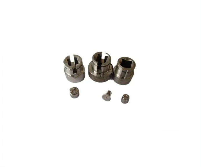
What push-button lock components convert into release or retention
The reference shows compact cylindrical and engaging forms that must be matched to the mechanism.
Button travel, guiding geometry and latch-connection interfaces
Provide button travel, guiding geometry and the connection to the latch or return element.
Identify the surfaces that locate the part and those that engage another member.
Why separate guide clearance from release travel?
Guide clearance permits movement, while travel determines whether the mechanism reaches its required positions.
One does not fully specify the other.
The drawing and assembly test should state both so a freely moving button is not mistaken for a correctly releasing lock.
MIM versus machining for integrated slots and connections
Compare MIM and machining for integrated slots and small connection features.
Sliding diameters or engaging surfaces may need finishing after forming.
Compare manufacturing capabilities →Lock component material, treated-surface and corrosion requirements
Specify the base material, final condition and corrosion or appearance requirements.
Mark drive, guiding and contact surfaces that must meet their dimensions after treatment.
Specify any testing required on the assembled lock separately.
Review material-selection information →Travel, return and guiding-clearance checks
Check travel, return, guiding clearance and engagement with the mating lock.
Define the operating test in the assembled condition.
Quality documentation →Push-button lock failures, and the narrow window between sticking and rattling
A push-button mechanism has an unpleasant property: the clearance that stops it sticking is the same clearance that lets it rattle. There is no single "good" number, only an allocation, and most field complaints come from that allocation never having been made explicitly.
| What goes wrong in service | What drives it | Where the drawing closes it out |
|---|---|---|
| The button sticks in humid weather | Two things close a guide in service: coating or oxide growth on the sliding faces, and contamination carried in by fingers. A guide with a long engagement length has more area to bind on, so the same clearance that works on a short guide fails on a long one. | Guide clearance allocated with the finish named, plus an explicit statement of the engagement length; verified by a push-return test after a humidity soak on assembled mechanisms, not on bare components. |
| The button does not return fully | A spring pocket whose floor is not flat makes the spring cock and lose effective travel. The mechanism still works, so the fault is reported as a soft or mushy button rather than as a defect. | Pocket floor flatness and the pocket depth related to the spring free length; verified on a sectioned sample and by a return-force measurement over the last part of the stroke. |
| The key override jams when the button is held in | This is a stack problem, not a part problem. The button travel and the latch retraction path share the same space, and each part can be in tolerance while the stack is not. | The mechanism defined on an assembly drawing with the stack called out, and the coupling geometry stated per part; verified by functional cycling with the button held during the override, which is the condition a single-part inspection never reproduces. |
| The button rattles when the lock is shaken | The other side of the same trade. If clearance was opened to cure a sticking complaint without also adding a biasing element, the button now has free play and the user hears it. | A stated maximum free play at the button face, and the return spring specified as the only element providing the bias; verified by a shake test that measures movement at the button, not at the mechanism inside. |
| A flat wears on the cam face | The cam nose is where force per unit area is highest in the whole lock, and it is usually the smallest feature on the part. A sharp nose wears to a flat, and the flat changes the travel-to-release relationship. | Cam nose radius and the surface condition of the rubbing face stated, with any hardening or treatment applied locally; verified by a cycling test to the intended life followed by measurement of the worn nose geometry. |
Use the project drawing for tolerances and acceptance limits.
Only two items here can be solved by making a part better. The cam nose is a geometry and treatment question, and the spring pocket floor is a tooling question. The sticking and rattle pair cannot be solved part by part at all: they are a clearance allocation across the mechanism, and treating them as a component complaint guarantees that fixing one creates the other. The override jam is the clearest case in this group for reviewing the assembly rather than the part print, because the condition that causes it exists for half a second during use and never during inspection.
What to include in your enquiry
- Drawing and mating dimensions.Provide button travel, guiding geometry and the connection to the latch or return element. Include the drawing revision.
- Mating information. Include the assembly references needed to define the interfaces discussed above.
- Delivered condition. State material, finishing and inspection requirements, identifying any items that need a manufacturing recommendation.
- Supply plan. Include sample needs, expected order and annual quantities, packaging requirements and target timing.
- First-sample inspection.Check travel, return, guiding clearance and engagement with the mating lock. Specify the mating part or inspection fixture.
Common questions
Does correct button travel guarantee latch release?
No. The connection, engagement geometry and return arrangement must also be verified with the complete mechanism.
Why separate guide clearance from release travel?
Guide clearance permits movement, while travel determines whether the mechanism reaches its required positions. One does not fully specify the other. The drawing and assembly test should state both so a freely moving button is not mistaken for a correctly releasing lock.
How should the completed mechanism be checked?
Check travel, return, guiding clearance and engagement with the mating lock. Define the operating test in the assembled condition.
Process and material references
Manufacturing and material references →Application and quotation details
- Describe button travel, contact surfaces and how the part is retained in the assembly.
- Define the reference faces and the clearance needed to move without interference.
- Agree finish, edge condition and sample checks against the actual mating components.
Related guide: MIM vs. CNC for Small Complex Metal Parts: A Drawing Review Checklist
Submit your drawing for a manufacturing-route review →