
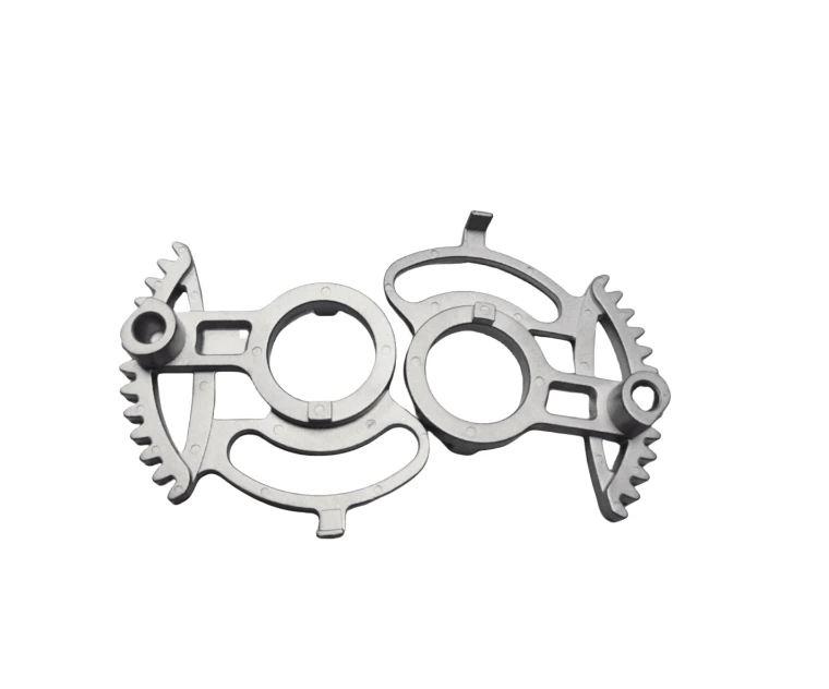
What a fingerprint-lock drive plate translates mechanically
The electronics do not remove the need to control the plate's geometry and contacts.
Pivot opening, cam profile and travel-limit interfaces
Define the pivot or drive opening, toothed or cam profile and travel limits.
Identify the mating actuator and locking member.
Why inspect the mechanical drive separately from the electronics?
The control system commands movement, but the plate and mating hardware must still engage and move correctly.
Their geometry can be checked against a defined mechanical arrangement.
Separating these requirements avoids relying on the electronic function to describe an unspecified mechanical fit.
Forming versus machining for plate profiles and openings
Compare forming and machining for the plate profile and integrated openings.
The chosen route should preserve functional edge geometry and flatness needed for movement.
Compare manufacturing capabilities →Fingerprint drive plate material, treated-surface and corrosion requirements
Specify the base material, final condition and corrosion or appearance requirements.
Mark drive, guiding and contact surfaces that must meet their dimensions after treatment.
Specify any testing required on the assembled lock separately.
Review material-selection information →The drive chain from motor travel to bolt travel
Electronics do not shorten this chain, they only move its input. The plate still has to convert a small motor movement into a bolt movement, and that conversion is where the accumulation lives.
| Link in the assembly chain | What it adds to the stack | Where to take it out of the chain |
|---|---|---|
| Pivot or drive opening | The pivot is the origin of the rotation the plate produces. Clearance at the opening becomes angular error at the cam, and angular error grows with distance from the pivot. | Reference the cam profile to the pivot rather than to the plate outline. On a rotating plate the outline is what the die makes; the pivot is what the assembly uses. |
| Cam profile | The profile converts angle into linear travel. Its shape error turns into a non-linear travel error, which is why a lock can work at one end of the stroke and bind at the other. | State the required travel at defined angular positions rather than tolerancing the profile alone. That converts a shape requirement into a function requirement the supplier can verify. |
| Travel limits | Limits are where the chain stops. If the limits are set by the housing rather than the plate, the plate only has to avoid interfering, and the whole link belongs to a different part. | Say which part owns the limit. Two parts both shaped to stop the travel will fight, and the loser is the one with the softer edge. |
| Actuator interface | The interface to the motor or solenoid carries the input position. A small offset here is amplified by the cam ratio. | Define the interface as a position, not as a clearance. The input side is the one place where a tight band is genuinely worth paying for. |
| Mechanical and electronic separation | The electronic package does not appear in the dimensional chain, but it constrains where the mechanical chain is allowed to sit. Mixing the two requirements into one tolerance makes neither checkable. | Keep the mechanical chain and the electrical requirement as separate sections of the drawing. They are verified by different methods and by different people. |
The assembly designer sets the tolerance allocation. Mark the controlling dimensions on the component drawing.
The reframe worth carrying: on a smart lock the mechanical chain is still a mechanical chain. It accumulates, it has a direction, and it fails at the end of the stroke. Electronics change the input and the diagnostics, not the arithmetic.
Profile-to-axis relationship and motion-range clearance checks
Check profile-to-axis relationship, engagement and clearance through the motion range.
Verify mechanical action independently of assumptions about the electronic control.
Quality documentation →What to include in your enquiry
- Drawing and mating dimensions.Define the pivot or drive opening, toothed or cam profile and travel limits. Include the drawing revision.
- Mating information. Include the assembly references needed to define the interfaces discussed above.
- Delivered condition. State material, finishing and inspection requirements, identifying any items that need a manufacturing recommendation.
- Supply plan. Include sample needs, expected order and annual quantities, packaging requirements and target timing.
- First-sample inspection.Check profile-to-axis relationship, engagement and clearance through the motion range. Specify the mating part or inspection fixture.
Common questions
Are the fingerprint electronics included with the drive plate?
No. Specify the metal component and its mechanical interfaces; electronic modules require a separate supply definition.
Why inspect the mechanical drive separately from the electronics?
The control system commands movement, but the plate and mating hardware must still engage and move correctly. Their geometry can be checked against a defined mechanical arrangement. Separating these requirements avoids relying on the electronic function to describe an unspecified mechanical fit.
How should the completed mechanism be checked?
Check profile-to-axis relationship, engagement and clearance through the motion range. Verify mechanical action independently of assumptions about the electronic control.