
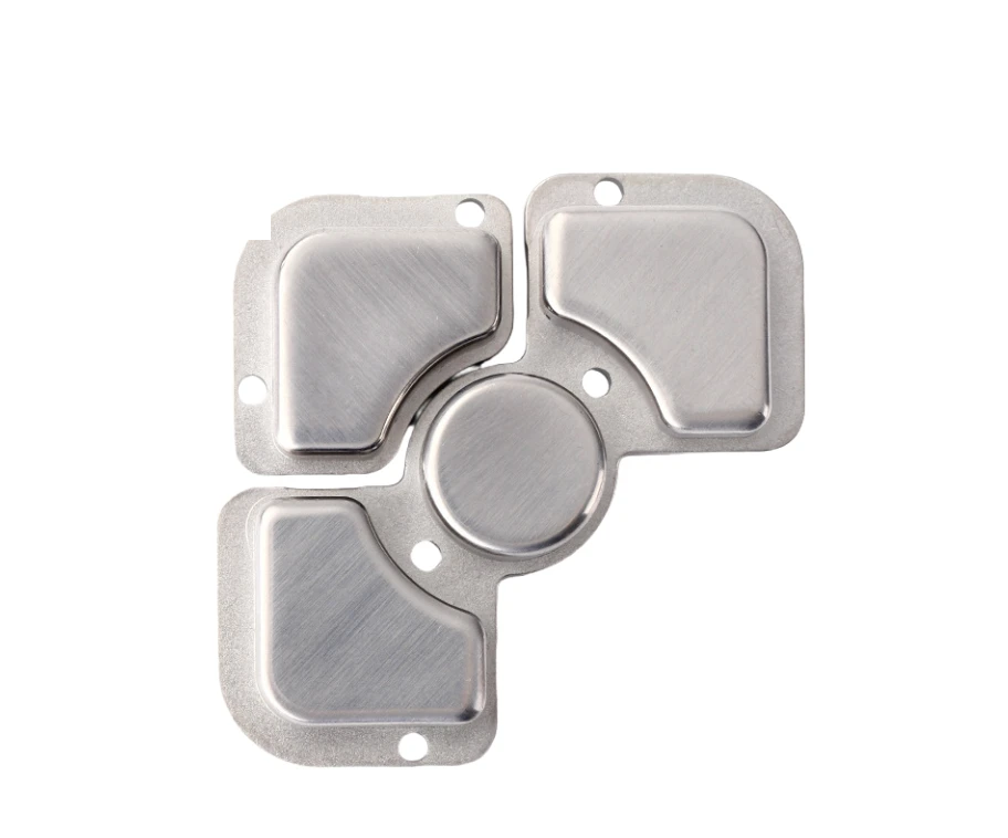
Product example
Metal Keyboard Buttons
Button and cover forms with visible exterior surfaces. Separate cosmetic requirements from locating and attachment features.
Consumer electronics components are the small metal parts in devices people handle every day — buttons and keys, hinges and pivot hardware, watch cases and attachment parts, camera mounts and compact structural fittings. SINTS produces these by metal injection molding (MIM), powder metallurgy (PM) or machining, with the choice driven by feature size, appearance requirements and annual volume.
Button and cover forms with visible exterior surfaces. Separate cosmetic requirements from locating and attachment features.
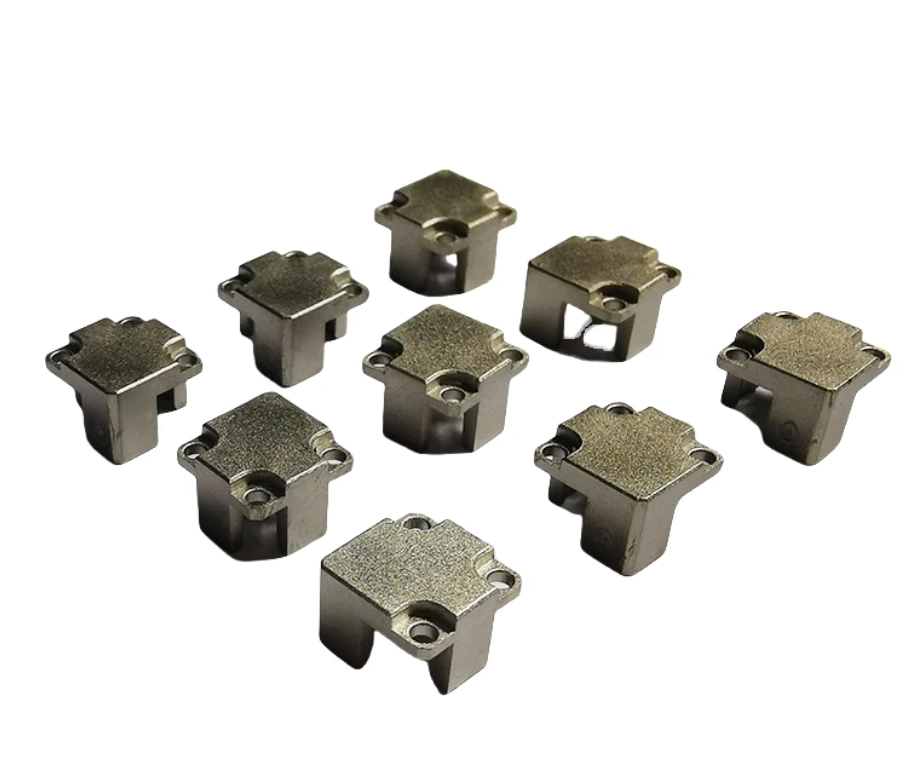
Compact metal parts with bosses, recesses and openings. Identify mounting datums and the surfaces that locate the part in the device.
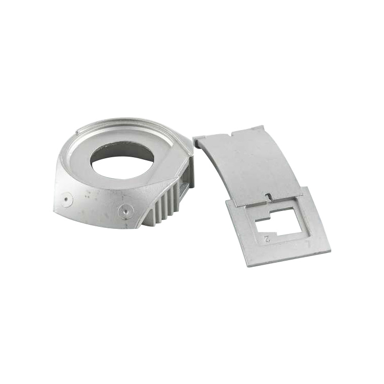
Case and fastening forms from the watch-parts catalog. Review exterior finish, openings and assembly interfaces on the actual drawing.
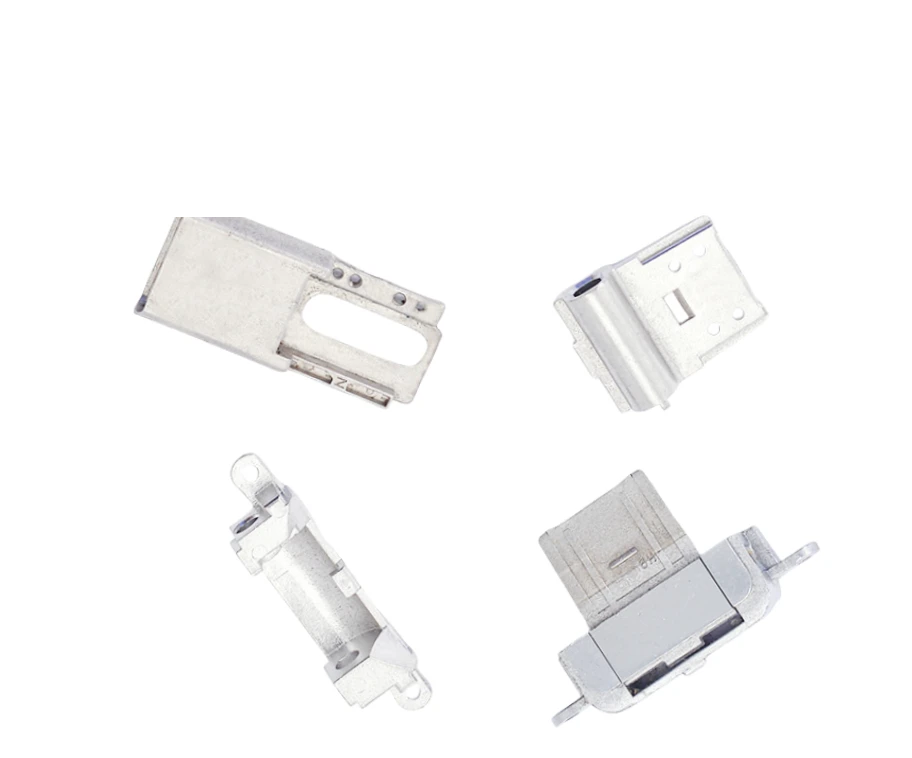
Small housing and support forms recorded as lens-related accessories. Clarify which faces locate or connect the component.
Examples from the SINTS product catalog, shown for component identification. These are custom parts, not stock specifications. Dimensions, material, supply scope and acceptance requirements are confirmed from your project drawing.
Explore each component in detail, including its interfaces, manufacturing review and drawing requirements.
The button examples combine thin outlines with exterior faces. A useful drawing identifies the visible side, permitted marks, edge condition and the features that locate the button in the housing. Finish samples help agree appearance before production.
Communication and camera components can combine holes, slots and bosses in a small envelope. Mark the assembly datums and critical fits before comparing forming and machining. The product photograph is a shape reference; it does not establish the dimensions or material for a new part.
The part drawing and its assembly determine the manufacturing route and the inspection plan.
Housing interfaces, locating datums, hole positions and clearances.
Visible faces, texture, color and acceptable cosmetic limits.
Walls, openings, edge condition and inspectable dimensions.
Fits after surface finishing and the agreed assembly checks.
Three reference tables for electronics hardware parts: the grades used for structure, appearance and thermal parts, where the forming routes stop, and the route from drawing to first article.
| Grade | Condition | Yield / UTS (MPa) | Elong. | Hardness | Density (g/cm³) | Why it is used here |
|---|---|---|---|---|---|---|
| 316L | Sintered | 250 / 498 | 40% | 110–160 HV | 7.75 | Visible frames and parts touched daily. Takes a polish or a brushed finish, and resists hand perspiration. |
| 17-4PH | Sintered → aged | 720 / 900 → 1070 / 1160 | 11% → 7% | 20–25 → 35–45 HRC | 7.50 | Hinges, latch cams and structural brackets that need strength in a thin section. |
| 6061 (AlSi10Mg) | Sintered | 100–350 / 900 | 10–15% | 40–60 HB | 2.70 | Weight-driven parts and heat spreaders. One third the density of steel, at the cost of strength and wear resistance. |
| T2 (C11000) | Sintered | 60–100 / 200–250 | 15–25% | 40–50 HRB | 8.60 | Electrical contacts, busbars and thermal parts where conductivity decides and strength does not. |
| 440C | Sintered | 1550 / 1750 | 1% | 58–62 HRC | 7.50 | Wear surfaces inside a mechanism: cam ramps, pivot pins and latch faces. |
| ZAMAK 3 (ZnAl4) | Die cast | 60–180 / 100–300 | 3–10% | 65–85 HB | 6.60 | Decorative shells and bezels at the lowest unit cost, when a plated or painted finish is acceptable. |
Density matters twice in this family: once as mass, and once as thermal mass. A copper heat spreader at 8.60 g/cm³ and an aluminium one at 2.70 g/cm³ solve the same thermal problem with opposite weight consequences, and the choice is usually made on the enclosure, not on the part.
| Requirement | Powder compaction | MIM | What it means here |
|---|---|---|---|
| Cosmetic surface | Pressed surfaces show die lines and need polishing or finishing | Moulded surfaces are finer, and a polished mould transfers its finish directly | A visible A-surface is usually a MIM part, or a machined part — compaction struggles to sell a cosmetic face |
| Thin wall in a shell | Set by fill, ejection and green strength; reviewed per part | 1–3 mm works comfortably; below about 0.5 mm cavity fill is at risk | Device shells sit right at the low end, which is where MIM earns its cost |
| General dimension, as sintered | Roughly ±0.3–0.5% of the dimension | Roughly ±0.3–0.5% of the dimension | A 2 mm snap feature cannot be held to a percentage of itself — it needs an absolute minimum agreed |
| Features tighter than about ±0.05 mm | Sizing or machining | Machining after sintering | Mating and datum features are finished; appearance features are formed |
| Ramp-up volume | Tooling-led; reviewed against annual demand | Tooling-led; reviewed against annual demand | Consumer programs ramp fast and end fast — tool life and cycle time matter as much as unit price |
Percentage tolerances follow the published MIM tolerance note. Small consumer parts expose the weakness of percentage tolerances most clearly: at 2 mm, ±0.5% is ten microns, which no forming route holds without a minimum absolute tolerance being agreed separately.
| Stage | Typical lead time | What you receive | What we need from you |
|---|---|---|---|
| Drawing review and DFM feedback | Issued with the quotation | Feature-by-feature route proposal, tolerance and finishing notes, and the open points that must be answered before tooling | 2D drawing with tolerances and datums, STEP model, target annual volume, material or the performance requirement |
| Tooling | 25–30 days as quoted on recent programs | Mould or die built and released to trial condition | Approval of the DFM report and confirmation of the alloy |
| T0 samples | 7–10 days after tooling release as quoted on recent programs | Parts plus a dimensional report against the drawing | Agreed inspection plan and datum scheme |
| Sizing, finishing and heat treatment | Runs inside or immediately after the sample stage | Sized and finished parts, hardness and density results where specified | Which features must be held after sintering, and which may be finished |
| First-article report | With the first approved samples | Dimensions, material, hardness and density measured in-house rather than subcontracted | Drawing with the critical characteristics marked |
| Production release | After sample approval | Serial production to the agreed inspection plan | Confirmed annual volume, MOQ and packaging |
Tooling and sample durations above are the lead times quoted on recent programs of comparable size, not a standard promise; the schedule for a specific part is confirmed with its quotation. Every result in the first-article report is measured on the instruments listed on the capabilities page.
Consumer electronics components are the small metal parts inside devices — buttons, hinges, wearable hardware and camera mounts. These answers cover process selection, appearance requirements and small-feature limits.
It is the small metal hardware inside or on a device: keycaps and buttons, hinge and pivot assemblies, watch cases, lugs and attachment links, camera lens-mount parts, sliders and compact structural fittings. These parts are usually small, produced in high volume and judged on appearance and feel as much as on dimension, which makes them a distinct family from structural industrial hardware.
Because the parts combine small size with genuinely three-dimensional geometry — an integrated boss, a captured pivot, a formed key profile — that would be costly to produce by milling at high volume. Near-net shaping produces that complexity in one tool, and where the part is also visible the surface condition then becomes a specified requirement rather than a by-product of the process.
Specify appearance as an explicit requirement with a reference: which surfaces are cosmetic, what the acceptable surface condition is, whether a specific finish, texture or colour is required, and how the part will be judged. On a visible button or watch part, an appearance standard is a functional requirement, and leaving it implicit is a common reason a dimensionally correct part is rejected at sample approval.
Very small features run into tooling, fill and ejection limits rather than a single size threshold. Fine pins, thin walls, sharp internal corners and deep narrow slots each behave differently across MIM, PM and machining, and the practical limit depends on the feature type and its relationship to the part as a whole. The sensible approach is to review the specific feature set on the drawing rather than apply a general minimum.
A button is judged on feel, travel, appearance and wear at the contact surface, while a structural part is judged on load, stiffness and fatigue. They are reviewed against different criteria even when they are the same size and material. Grouping them as one request tends to blur the requirements, so stating each part's function separately makes the review more accurate.
Include the mating housing, critical dimensions, visible surfaces, finish requirements and annual quantity.