
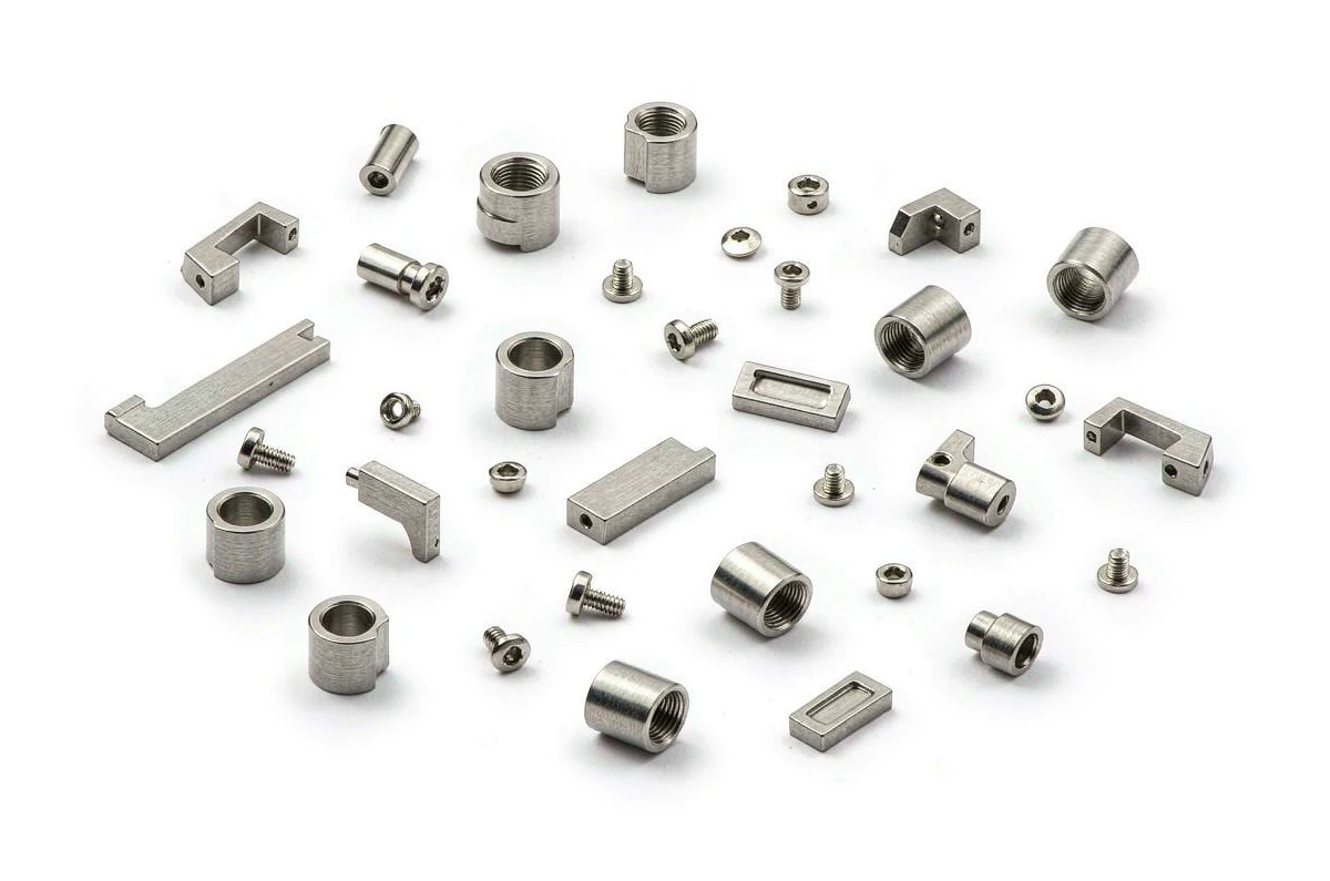
What eyewear fittings join and retain in a compact space
The focus is the small mechanical interface, not a claim that a generic metal collection is an exact eyewear drawing.
Frame, temple, pivot and stop interfaces
Provide the frame and temple interfaces, pivot arrangement and any adjustment or stop feature.
Identify surfaces exposed to the user and the required finish.
Why distinguish frame attachment from pivot movement?
The attachment locates the fitting on the frame, while a pivot may establish movement.
Combining them into one general fit requirement hides the different surfaces that control each.
The frame and temple drawings provide the references needed to assess both.
MIM versus machining for integrated eyewear shapes
Compare MIM for integrated small shapes with machining or other suitable forming routes.
Pin holes and working contacts may need post-forming finishing.
Compare manufacturing capabilities →Eyewear fitting material, exposed-surface and finish requirements
Define base material, final condition and cosmetic finish separately.
Identify visible faces, permitted edge rounding and the dimensions that must be met after finishing.
Any magnetic, electrical or acoustic requirement needs its own specification.
Review material-selection information →Attachment fit, pivot movement and finished-appearance checks
Check attachment fit, pivot movement, edges and appearance after finishing.
Use the actual mating frame for the agreed operating test.
Quality documentation →Where thin stainless parts move between press and furnace
Frame hardware is small, thin, and visible at close range. Those three together are the hardest combination in this route, and the changes below are what usually has to be conceded to get a part that is straight and can be finished.
| What we flag | Why it bites on this part | How the drawing usually changes |
|---|---|---|
| Length to thickness ratio | A slender part sags under its own weight at sintering temperature. Nothing in the tool can prevent it; only the way it is supported in the furnace can. | The part is designed to be sintered flat on its widest face, and a support rib is added that is removed after, or the geometry is split so no single piece is longer than about 10 times its thickness. |
| Hinge bores | A bore that is sintered to final size carries the same radial spread as any other diameter, and a hinge screw needs better than that or it rattles. | The bore is called with a reaming allowance and reamed after sintering, which also cleans the porosity at the bearing surface. |
| The joining feature | Laser welding and riveting both need a defined interface. A butt joint on a 0.8 mm section does not have the strength the design assumes. | A boss, a lap or a tab is added to the drawing so the joint has area, and the drawing names the joining process so the feature is sized for it. |
| Mirror polish | Sintered surfaces have open porosity, and porosity shows up at the end of a polishing sequence as tiny pits. A mirror finish on a sintered part is a density requirement as much as a finishing one. | The polish spec comes with a density floor and a Ra target, or the visible faces are machined before polishing. |
| Target weight | Stainless is roughly twice the density of titanium, and on a frame the weight is a market requirement rather than an engineering preference. | Where the weight is firm, titanium MIM is priced alongside stainless from the start instead of being raised after the design is frozen. |
Confirm any proposed change against your assembly requirements.
The suggestion we withdraw most often is the one about tighter straightness. Straightening a sintered part is a real operation, but it adds a manual step and it does not hold after the part is heat treated or welded. If straightness is critical, it belongs in the design as a stiffer section, not in the inspection as a tighter number.
What to include in your enquiry
- Drawing and mating dimensions.Provide the frame and temple interfaces, pivot arrangement and any adjustment or stop feature. Include the drawing revision.
- Mating information. Include the assembly references needed to define the interfaces discussed above.
- Delivered condition. State material, finishing and inspection requirements, identifying any items that need a manufacturing recommendation.
- Supply plan. Include sample needs, expected order and annual quantities, packaging requirements and target timing.
- First-sample inspection.Check attachment fit, pivot movement, edges and appearance after finishing. Specify the mating part or inspection fixture.
Common questions
Can eyewear hardware be selected by visual resemblance?
No. Frame connection, pivot geometry and user-contact requirements must be confirmed for the intended model.
Why distinguish frame attachment from pivot movement?
The attachment locates the fitting on the frame, while a pivot may establish movement. Combining them into one general fit requirement hides the different surfaces that control each. The frame and temple drawings provide the references needed to assess both.
How are appearance and functional fit checked?
Check attachment fit, pivot movement, edges and appearance after finishing. Use the actual mating frame for the agreed operating test.