
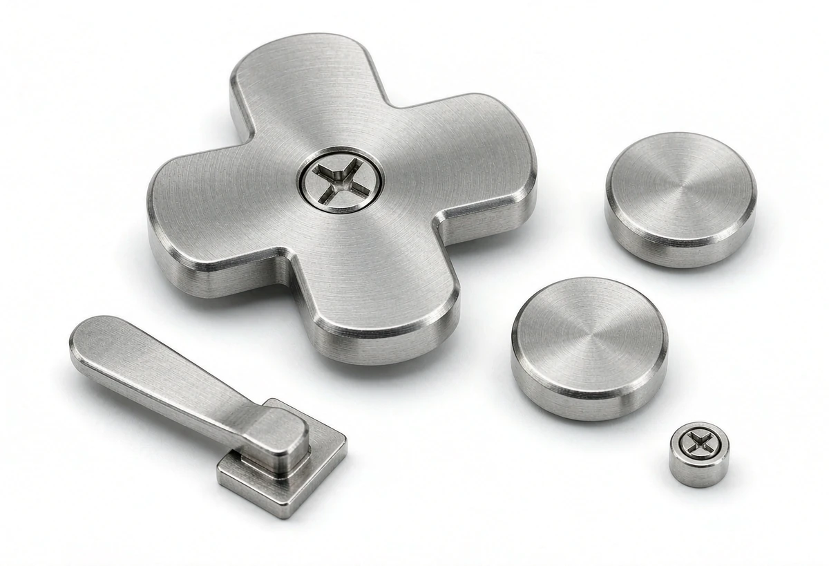
What controller buttons combine on the user face and guide features
The illustrated metal button shapes are a related reference, not a branded controller specification.
Keycap outline, guide features and travel-limit interfaces
Define the keycap outline, guide features, travel limits and connection to the switch or mechanism.
Symbols and visible finishes are separate customer-defined requirements.
Why separate button travel from cosmetic shape?
The exterior face is the user's contact surface, but the guide and stop features determine how the button moves.
A cosmetic match does not confirm either travel or retention.
The drawing should make the operating features visible alongside the appearance requirements.
MIM versus machining for guide and retention geometry
Compare MIM or machining for the guide and retention geometry.
The finishing sequence must preserve sliding clearances and avoid unwanted edge rounding at functional features.
Compare manufacturing capabilities →Button base material, cosmetic finish and travel requirements
Define base material, final condition and cosmetic finish separately.
Identify visible faces, permitted edge rounding and the dimensions that must be met after finishing.
Any magnetic, electrical or acoustic requirement needs its own specification.
Review material-selection information →Housing clearance, return movement and retention checks
Check housing clearance, return movement, retention and agreed visual appearance.
Evaluate the button with the actual switch and surrounding housing.
Quality documentation →What a gaming button has to trade for feel
A button is judged by a hand, not by a micrometer, and the two do not measure the same thing. The changes below are the ones that decide whether the part feels right after the tool is cut, because after that point feel is not adjustable.
| What we flag | Why it bites on this part | How the drawing usually changes |
|---|---|---|
| Guide length against button diameter | If the guide is shorter than about 1.5 times its diameter, the cap rocks in the bore and the press feels loose at one edge before it feels tight at the other. | The guide section is lengthened, or the bore is moved to a second part so the length can be added without changing the cap. |
| The face the silicone dome pushes against | The return force comes from a dome underneath, and the dome only behaves repeatably if the face it presses is flat and square to the travel. | The contact face gets a flatness call and a shallow recess, so the dome locates instead of sliding. |
| Legend and icon depth | Engraving 0.1 mm deep on a sintered cap closes up in some lots and reads as a blank button in others. | The legend becomes a shallow engraved pocket at 0.15 mm or a double-shot plastic insert, not a line engraving. |
| Cap wall thickness | Below about 0.8 mm the cap distorts during sinter and the top is no longer flat, which shows immediately under a light. | The wall is brought to 0.8 mm minimum, and if the weight matters a pocket is added inside instead. |
| A set of buttons on one tool | Buttons in a set share one shrink rate if they share one tool. Moulded on different tools, they no longer agree on size. | The set is called as one tool with shared cavities, and the drawing groups the buttons rather than listing them as separate parts. |
Confirm any proposed change against your assembly requirements.
We do not argue with a feel requirement, but we do ask for it to be written as something measurable: travel, breakaway force, return force, wobble. A drawing that says "premium feel" hands the acceptance decision to whoever inspects it that day, and that is a worse risk than a tight tolerance.
What to include in your enquiry
- Drawing and mating dimensions.Define the keycap outline, guide features, travel limits and connection to the switch or mechanism. Include the drawing revision.
- Mating information. Include the assembly references needed to define the interfaces discussed above.
- Delivered condition. State material, finishing and inspection requirements, identifying any items that need a manufacturing recommendation.
- Supply plan. Include sample needs, expected order and annual quantities, packaging requirements and target timing.
- First-sample inspection.Check housing clearance, return movement, retention and agreed visual appearance. Specify the mating part or inspection fixture.
Common questions
Are controller symbols or brand markings included?
No. Any marking, layout and approval must be supplied for the specific project; the component reference does not authorize branded reproductions.
Why separate button travel from cosmetic shape?
The exterior face is the user's contact surface, but the guide and stop features determine how the button moves. A cosmetic match does not confirm either travel or retention. The drawing should make the operating features visible alongside the appearance requirements.
How are appearance and functional fit checked?
Check housing clearance, return movement, retention and agreed visual appearance. Evaluate the button with the actual switch and surrounding housing.