
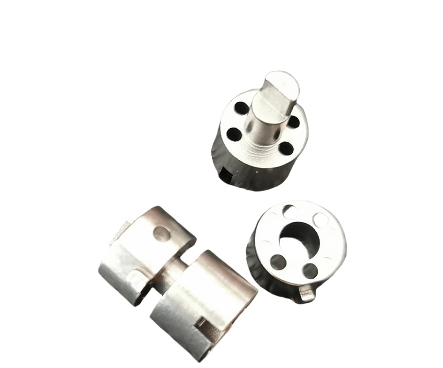
What compact mounting parts do in an electronic assembly
The reference includes round and slotted forms whose function must be identified on the assembly drawing.
Primary locating axis, face and secondary-opening interfaces
Define the primary locating axis or face before specifying the secondary openings.
Clearly distinguish holes used for attachment from those used for alignment or clearance.
Why identify a primary locating feature first?
A compact component may have several holes and projections without all of them locating the assembly.
Naming the primary axis or face gives the secondary features a consistent reference.
It also helps distinguish an alignment requirement from a simple clearance requirement.
MIM versus machining for integrated small features
Compare MIM for integrated small features with machining for straightforward turned or milled shapes.
Plan final operations where mounting interfaces require tighter control.
Compare manufacturing capabilities →Mounting-part base material and finish requirements
Define base material, final condition and cosmetic finish separately.
Identify visible faces, permitted edge rounding and the dimensions that must be met after finishing.
Any magnetic, electrical or acoustic requirement needs its own specification.
Review material-selection information →Where the stack closes in a compact electronic assembly
Compact assemblies fail on accumulation more often than on any individual tolerance. The parts in this group each occupy one link, and the useful question is not how tight each one is but which one is meant to stay loose.
| Link in the assembly chain | What it adds to the stack | Where to take it out of the chain |
|---|---|---|
| Primary locating axis or face | The primary locating feature sets the origin for every secondary opening. A shift here moves the whole pattern, so it appears as one error rather than as many. | Name the primary datum explicitly on the drawing. When it is left to whoever makes the part, two suppliers will pick different faces and both will be defensible. |
| Secondary openings | A secondary opening carries the position error of the primary plus its own. In a chain of three openings the last one holds the sum. | Where an opening is a clearance hole, let it stay loose on purpose and say so. Tightening a clearance hole removes the float the assembly needs and transfers the error elsewhere. |
| Stack height across the parts | Height accumulates linearly through every part in series. A three-part stack triples the contributors while each one still looks acceptable on its own certificate. | Decide in advance which part in the series is the adjustment link. Without a designated link, the assembly is closed by force, and force leaves a witness mark somewhere. |
| Clearance hole against thread | The difference between the clearance and the fastener is the intended float. It is the cheapest link to give freedom to, because it costs nothing to widen. | Keep that float available rather than closing it with a tighter hole. A part toleranced so tightly that it must be pressed in turns an assembly step into a rework step. |
| Surface condition after finishing | Plating and passivation add thickness on every face at once. If the drawing measures after finishing it is a different part from the one measured before. | State the condition of measurement on each critical dimension. This one line removes an entire category of dispute, and it costs nothing to add. |
The assembly designer sets the tolerance allocation. Mark the controlling dimensions on the component drawing.
The reframe this page is after: in a compact assembly, a part is not judged on its own tolerance but on whether it is the link designed to move. Two parts at the same tolerance can be right and wrong respectively, depending on which role each was given.
Datum relationships, opening positions and enclosure-fit checks
Inspect datum relationships, opening positions and the final fit inside the enclosure.
State any magnetic, electrical or cosmetic requirements explicitly.
Quality documentation →What to include in your enquiry
- Drawing and mating dimensions.Define the primary locating axis or face before specifying the secondary openings. Include the drawing revision.
- Mating information. Include the assembly references needed to define the interfaces discussed above.
- Delivered condition. State material, finishing and inspection requirements, identifying any items that need a manufacturing recommendation.
- Supply plan. Include sample needs, expected order and annual quantities, packaging requirements and target timing.
- First-sample inspection.Inspect datum relationships, opening positions and the final fit inside the enclosure. Specify the mating part or inspection fixture.
Common questions
Can a metal mounting part also serve an electrical function?
Possibly, but conductivity, grounding or shielding requirements must be specified and verified rather than inferred from the material appearance.
Why identify a primary locating feature first?
A compact component may have several holes and projections without all of them locating the assembly. Naming the primary axis or face gives the secondary features a consistent reference. It also helps distinguish an alignment requirement from a simple clearance requirement.
How are appearance and functional fit checked?
Inspect datum relationships, opening positions and the final fit inside the enclosure. State any magnetic, electrical or cosmetic requirements explicitly.