
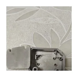
What notebook hinge components guide between display and base
Review this component together with its mating parts and delivered condition. The interfaces below define the drawing information needed to assess forming, finishing and inspection.
A hinge can contain multiple metal parts whose individual tolerances contribute to the finished motion.
Pivot arrangement, mounting hole pattern and stop interfaces
Supply the pivot arrangement, mounting hole pattern and stop geometry.
Identify the part responsible for location separately from friction or preload elements.
Why specify the hinge as a set of interfaces?
A hinge often contains brackets, axes and friction or retention members.
Their combined behavior cannot be assigned to one part without defining how they interact.
Interface drawings make each component's contribution clear and support a meaningful assembled movement check.
MIM, machining and stamping for hinge shafts and brackets
Compare MIM for integrated small fittings with machining, stamping or other routes for shafts and brackets.
A complete hinge is not necessarily made by one process.
The proposed route is confirmed for your drawing, material and quantity. An image does not establish a fixed tolerance or a complete process specification.
Compare manufacturing capabilities →Notebook hinge base material and cosmetic-finish requirements
Define base material, final condition and cosmetic finish separately.
Identify visible faces, permitted edge rounding and the dimensions that must be met after finishing.
Any magnetic, electrical or acoustic requirement needs its own specification.
Review material-selection information →Mounting alignment, travel limits and finished-clearance checks
Check mounting alignment, travel limits and finished clearances.
Torque and cycle testing must be defined for the complete hinge arrangement.
Specify the drawing revision and the condition in which each dimension is inspected. Record the agreed dimensional and functional checks before sample approval.
Quality documentation →Prepare a Product-Specific RFQ
- Component definition. Send the 2D drawing and 3D model, where available, with the drawing revision and the requested part or assembly scope.
- Mating information. Include the assembly references needed to define the interfaces discussed above.
- Delivered condition. State material, finishing and inspection requirements, identifying any items that need a manufacturing recommendation.
- Supply plan. Include sample needs, expected order and annual quantities, packaging requirements and target timing.
Product Questions
Can hinge torque be specified on the bracket drawing alone?
The bracket can carry interface requirements, but torque also depends on friction, preload and the assembled mechanism.
Why specify the hinge as a set of interfaces?
A hinge often contains brackets, axes and friction or retention members. Their combined behavior cannot be assigned to one part without defining how they interact. Interface drawings make each component's contribution clear and support a meaningful assembled movement check.
How are appearance and functional fit checked?
Check mounting alignment, travel limits and finished clearances. Torque and cycle testing must be defined for the complete hinge arrangement.
Technical Context
The product-specific notes above identify drawing-review questions. General process and material references are collected separately; they do not verify a material grade, production qualification or performance claim for the pictured part.
Manufacturing and material references →