
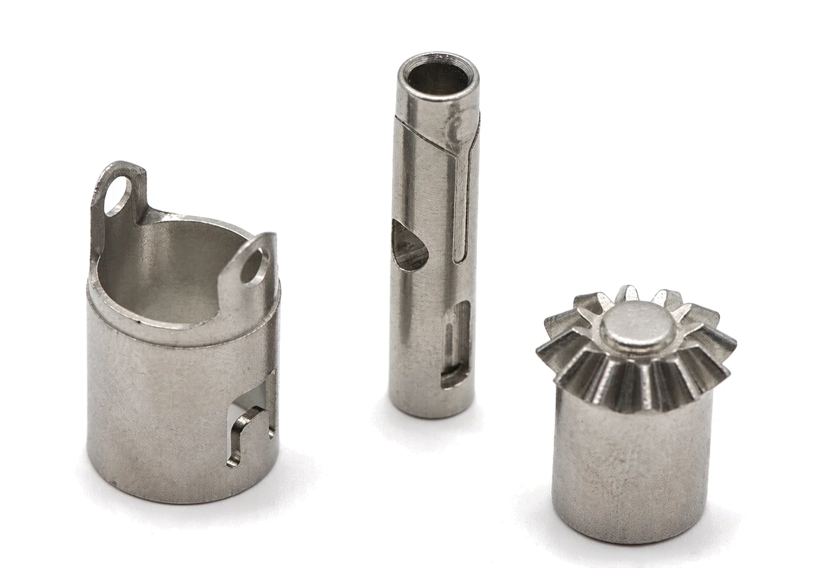
What structural metal parts provide in a phone-related assembly
Review this component together with its mating parts and delivered condition. The interfaces below define the drawing information needed to assess forming, finishing and inspection.
The source group is a geometry reference; the actual device interface must be specified.
Component identity, attachment and device interfaces
Identify the exact component and its attachment to the device.
For a shaft or sleeve form, define the axis and shoulders; for a support, define the locating faces.
Why identify the actual component before choosing PM?
A reference group can include shapes with very different manufacturing needs.
A shaft, sleeve and support are not one process specification.
Identifying the exact component first allows material, geometry and final interfaces to drive the route comparison.
Conventional PM versus machining for actual sections
Compare conventional PM, machining and other forming methods against the actual section and features.
A process label is not a final route decision for a new drawing.
The proposed route is confirmed for your drawing, material and quantity. An image does not establish a fixed tolerance or a complete process specification.
Compare manufacturing capabilities →Structural part base material and finish requirements
Define base material, final condition and cosmetic finish separately.
Identify visible faces, permitted edge rounding and the dimensions that must be met after finishing.
Any magnetic, electrical or acoustic requirement needs its own specification.
Review material-selection information →Confirm which link this part is before closing the chain
This entry covers a geometry family rather than one identified component, so the dimensional chain cannot be closed yet. What can be done usefully is to establish which link the part occupies, because that decides what the tolerance has to mean.
| Link in the assembly chain | What it adds to the stack | Where to take it out of the chain |
|---|---|---|
| Component identity | An unidentified part cannot enter a chain at all. Nothing downstream can be calculated, because it is not known whether the part locates, spaces, clamps or only covers. | Identify the exact component and its mating parts before any route discussion. A geometry reference supports a feasibility conversation; it does not support a dimensional one. |
| Attachment to the device | The attachment face is the origin of the chain for this part. If it is not a single face, the part has two competing origins and the chain has an ambiguity that no tolerance can resolve. | Name one attachment face as the primary datum and make the rest secondary. Where two faces both qualify, state which one wins when they disagree. |
| Axis and shoulder for shaft and sleeve forms | For a rotational form the axis is the link, and the shoulders are positions along it. Coaxiality and shoulder spacing are separate links and they are often confused. | Tolerance the shoulders from the same axis datum rather than from each other. Chained shoulder dimensions accumulate; datum-referenced ones do not. |
| Section changes | A change of section is where flatness and straightness are lost first, and where a forming route has to decide whether to press in one direction or add a second operation. | State whether the section change is functional or cosmetic. If it is functional, it belongs in the tolerance scheme; if it is cosmetic, it should not be allowed to drive the process choice. |
| Delivered surface condition | Coating and passivation move every dimension at once, and on a thin part they move it proportionally more. The chain should record which state the numbers were measured in. | Write the condition of measurement against each critical dimension. Without it the same part can pass at the supplier and fail at the assembly line and both measurements can be correct. |
Note. The links below describe how error accumulates in an assembly, not how to allocate tolerance for a specific drawing. Which link should carry the accumulation is a design decision that belongs to whoever owns the assembly; the supplier can only hold what the drawing names. Nothing here states an achievable tolerance for any dimension.
The practical next step for this family is a single drawing of the actual component with its mating parts named. Once that exists, the chain is short and the process question answers itself; until it exists, every comparison is between geometries rather than between parts.
Locating geometry, clearance and final-condition checks
Check the chosen component's locating geometry, clearances and final condition.
Do not transfer specifications between different forms in the source group.
Specify the drawing revision and the condition in which each dimension is inspected. Record the agreed dimensional and functional checks before sample approval.
Quality documentation →Prepare a Product-Specific RFQ
- Component definition. Send the 2D drawing and 3D model, where available, with the drawing revision and the requested part or assembly scope.
- Mating information. Include the assembly references needed to define the interfaces discussed above.
- Delivered condition. State material, finishing and inspection requirements, identifying any items that need a manufacturing recommendation.
- Supply plan. Include sample needs, expected order and annual quantities, packaging requirements and target timing.
Product Questions
Does a PM label fix the process for a new phone part?
No. The new geometry, material and quantity still require an independent manufacturing review.
Why identify the actual component before choosing PM?
A reference group can include shapes with very different manufacturing needs. A shaft, sleeve and support are not one process specification. Identifying the exact component first allows material, geometry and final interfaces to drive the route comparison.
How are appearance and functional fit checked?
Check the chosen component's locating geometry, clearances and final condition. Do not transfer specifications between different forms in the source group.
Technical Context
The product-specific notes above identify drawing-review questions. General process and material references are collected separately; they do not verify a material grade, production qualification or performance claim for the pictured part.
Manufacturing and material references →