
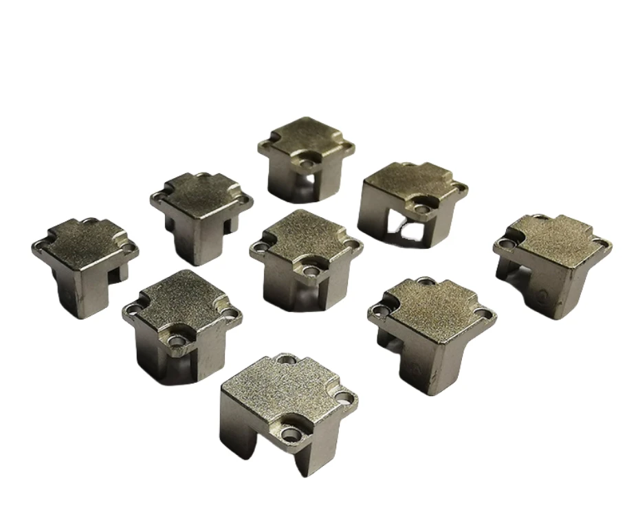
What communication-device components combine in a small envelope
Review this component together with its mating parts and delivered condition. The interfaces below define the drawing information needed to assess forming, finishing and inspection.
Their fit to neighboring parts is the starting point for manufacturing review.
Locating faces, bosses and enclosure interfaces
Define the locating faces and the relationship between bosses, holes and the device enclosure.
Identify any separate electrical, magnetic or appearance requirement.
Why list electrical requirements separately from mechanical fit?
A part may mount correctly without meeting a specified contact or electrical function.
Conversely, a material choice made for an electrical requirement still needs to fit the enclosure.
Separate requirements allow the manufacturing proposal and acceptance plan to address both functions explicitly.
MIM versus CNC for compact and accessible geometry
Compare MIM for integrated compact geometry with CNC for simple accessible features.
Critical assembly dimensions may need controlled machining after forming.
The proposed route is confirmed for your drawing, material and quantity. An image does not establish a fixed tolerance or a complete process specification.
Compare manufacturing capabilities →Which process actually suits this communication-device part
At this size, four processes are normally quoted side by side. Each wins on a different combination of section thickness, annual volume, and how much of the geometry sits on one axis. The rows below state the condition under which each one wins on this part, not which one is better.
| Alternative process | When it wins on this part | What puts sintering back in front |
|---|---|---|
| Progressive stamping from strip | Wins whenever the thickness is uniform and every feature can be developed flat and then bent. Per-piece cost at high volume is far below any forming route. | Once the drawing shows a local thickening, a blind pocket, or a boss that must stand normal to the strip face, bending cannot produce it. That is where sintering stops competing on price and starts competing on part count. |
| Zinc die casting | Wins when the part is the shell around the module and the wall still fills reliably at that section. Tool life is long and trimming is cheap. | At this envelope the wall usually falls to the side where zinc will not fill, and the gate mark lands on a mating face. Sintering earns its place here on wall uniformity across the shield cavity, not on piece price. |
| CNC from bar or plate | Wins from prototype through low volume, with no tooling to amortise and no material lot to commit to. | The changeover belongs to the annual quantity that can absorb the press tool, combined with geometry that needs several non-orthogonal setups on a mill. Say that volume threshold in the first exchange instead of at quotation. |
| Swiss screw machining | Wins on the cylindrical connector body where bores are coaxial and concentricity is the controlling callout. One setup holds the relationship. | A side slot, a flat, or a radial hole forces a second clamping and re-datuming. Once two or three of those appear on the same body, forming them in one cycle is what the decision turns on. |
| Investment casting | Wins on the larger bracket that carries the module when the section is too heavy for sintering to be economic and the tolerance is loose enough to absorb wax-tool variation. | If the aperture that locates the module also has to align with the housing, cast scatter turns into part-to-part sorting. That sorting cost is not visible in the casting quote. |
Note. This table is a screening aid, not a recommendation against our own process. Where a row above describes your part better than the sintering route does, we will say so and quote against the route that actually fits; the quantities, alloy and tolerances on your drawing still decide the answer.
The point of this table is not to defend a route. It is so that a buyer can tell in the first exchange whether this enquiry belongs with us at all. If two rows above describe the part, say so and we will tell you which of the two we would quote against.
Communication-device component material and finish requirements
Define base material, final condition and cosmetic finish separately.
Identify visible faces, permitted edge rounding and the dimensions that must be met after finishing.
Any magnetic, electrical or acoustic requirement needs its own specification.
Review material-selection information →Mounting relationship, edge condition and device-clearance checks
Check mounting relationships, edge condition and device clearance.
Confirm whether finish is cosmetic or has a separate functional requirement.
Specify the drawing revision and the condition in which each dimension is inspected. Record the agreed dimensional and functional checks before sample approval.
Quality documentation →Prepare a Product-Specific RFQ
- Component definition. Send the 2D drawing and 3D model, where available, with the drawing revision and the requested part or assembly scope.
- Mating information. Include the assembly references needed to define the interfaces discussed above.
- Delivered condition. State material, finishing and inspection requirements, identifying any items that need a manufacturing recommendation.
- Supply plan. Include sample needs, expected order and annual quantities, packaging requirements and target timing.
Product Questions
Should conductivity or shielding be assumed from a metal part?
No. Such requirements need their own material, contact and verification specifications.
Why list electrical requirements separately from mechanical fit?
A part may mount correctly without meeting a specified contact or electrical function. Conversely, a material choice made for an electrical requirement still needs to fit the enclosure. Separate requirements allow the manufacturing proposal and acceptance plan to address both functions explicitly.
How are appearance and functional fit checked?
Check mounting relationships, edge condition and device clearance. Confirm whether finish is cosmetic or has a separate functional requirement.
Technical Context
The product-specific notes above identify drawing-review questions. General process and material references are collected separately; they do not verify a material grade, production qualification or performance claim for the pictured part.
Manufacturing and material references →