
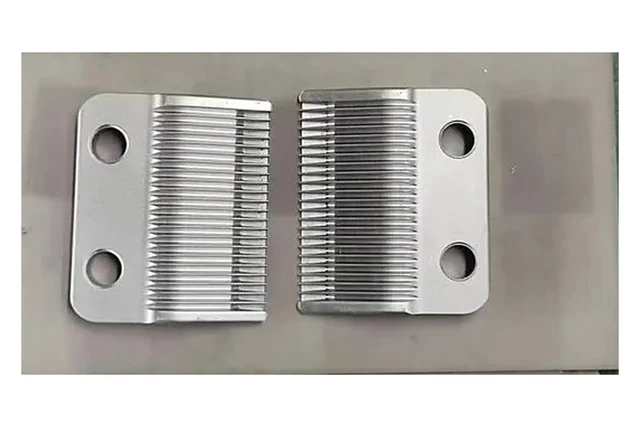
Cutting-blade references
Tooth profile, flatness, cutting edge and final grinding need to be defined with the material and duty.
Discuss a similar component →Cutting and contact geometries reviewed for edge condition, hardness, toughness and finishing requirements.
Tooth profile, flatness, cutting edge and final grinding need to be defined with the material and duty.
Discuss a similar component →Representative custom component references. Dimensions, material, manufacturing route and validation requirements are confirmed from your drawing; these are not off-the-shelf catalog items.
Edges and tooth profiles where hardness, toughness, flatness and sharpening dominate.
Compact parts that see repeated sliding, abrasion or hard contact.
Teeth or contact features that need hardness and wear resistance.
Stops, noses or inserts where impact and local contact stress drive material and finishing.
| Review area | Information to define | Manufacturing decision |
|---|---|---|
| Edge geometry | Profile, edge angle, burr direction, sharpness and mating cutting member. | Plan sharpening or grinding and the inspection method for the finished edge. |
| Wear mechanism | Abrasion, sliding, impact, contact stress, lubricant and mating material. | Choose the material system for the actual wear mode rather than hardness alone. |
| Heat treatment | Required hardness range, toughness, distortion and final datum condition. | Evaluate the sequence of heat treatment, grinding and straightness checks. |
| Validation | Cutting duty, cycle target, fracture limits and component/assembly test responsibility. | Agree a qualified sample and functional verification plan before production. |
Material & final condition. Tool steel, stainless or specialty materials require exact grade and condition confirmation. Tungsten alloys and tungsten carbide are different material systems. MIM is assessed only where geometry, material and volume support the route. Review material data →
| Component / condition | First route to evaluate | Why / watchout |
|---|---|---|
| Thin blade / cutter | Stamping / machining + heat treatment | Thin cutting geometry usually favors established blade/tool-steel routes; edge grinding and distortion control are critical. |
| Small complex wear insert | MIM + heat treatment / finishing | MIM may help when 3D geometry is complex and volume is high, but wear surfaces and toughness must be validated. |
| Simple hard pin / wear pad | Machining / grinding | Simple geometry with demanding hardness or finish often favors direct machining. |
| Tungsten / specialty wear component | Project-specific specialty route | Exact material, binder, density, brittleness and finishing must be confirmed; do not generalize from “tungsten steel” alone. |
| Low-volume custom cutter | CNC / EDM / grinding | Tooling economics often favor direct processes. |
Boundary: blades and safety-critical cutting elements need specialist material, heat-treatment, edge and system validation. MIM is only one possible manufacturing route for selected complex wear parts.
Review geometry, material and volume, identify critical features and clarify the proposed tooling and secondary operations.
Define trial parts, dimensional checks, material confirmation and any customer-required functional approval.
Confirm the approved route, control plan, packaging and repeat-supply requirements for the program.
Nose inserts, jaws and repeated-impact wear parts.
Application guide →Blade systems and hard-contact mechanism interfaces.
Application guide →Outdoor drive and wear components; cutting safety remains a system-level topic.
Application guide →Jaws and contact/wear interfaces in repeated gripping cycles.
Application guide →Send the edge/contact drawing, mating material, wear or cutting duty, hardness/toughness target, finishing and annual quantity.