
Pneumatic nailers & staplers
Valve stems/seats, trigger links, pawls, latches, depth-adjuster parts and nose-guide inserts are more relevant to MIM than large cylinders or magazines.
These tools turn stored pneumatic, electric or mechanical energy into repeated fastening cycles. Small pawls, latches, valve parts, depth adjusters, gears, cams and riveting jaws can be attractive MIM or PM candidates — while driver blades, large cylinders, magazines, springs and seals usually belong to other processes.
Manufacturing reference: Representative SINTS components are shown to illustrate compact mechanism, linkage and gear geometries relevant to fastening-tool engineering reviews. Final process selection depends on the actual drawing, impact load, wear, tolerances and production volume.
The handbook separates pneumatic fastening tools, cordless architectures and riveting tools because their load paths and failure modes are not the same.
Valve stems/seats, trigger links, pawls, latches, depth-adjuster parts and nose-guide inserts are more relevant to MIM than large cylinders or magazines.
Motor-driven flywheel, spring or gas-spring architectures add gears, cams, clutch parts, ratchets and compact guides that increase the number of small high-load metal components.
Jaws, jaw cases, nosepiece parts, pull-mechanism components and wear interfaces see repeated high axial loads and need careful material and heat-treatment selection.
Pawls, latches, trigger links, contacts and depth mechanisms influence jam rate, actuation logic and repeatability; small geometry can be attractive for near-net-shape production.
| Component | Function | First route to evaluate | Why / watchout |
|---|---|---|---|
| Trigger link / pawl / latch | Actuation, lockout or feed control | MIM — high potential | Compact feature-rich geometry can replace multiple machining steps; pin bores, wear faces and fatigue require review. |
| Depth-adjuster component | Controls drive depth or stop position | MIM — often worth evaluating | Small cams, detents and irregular profiles can suit MIM if platform volume is stable. |
| Valve stem / seat insert | Controls pneumatic flow | Turning / MIM + finishing / CNC | Simple rotational stems favor turning; integrated geometry may justify MIM, but sealing surfaces must be finished and validated. |
| Gear / cam / ratchet | Cordless transmission or energy release | PM / MIM / gear process | Tooth load, density, wear, noise and impact determine the route; some parts need heat treatment or secondary finishing. |
| Riveter jaw / jaw carrier | Grips mandrel under axial load | MIM / CNC + heat treatment | Small complex geometry can suit MIM, but gripping teeth, hardness, fatigue and wear are critical. |
| Nose guide insert | Guides fastener / supports wear zone | MIM / CNC / tool-steel process | Wear, impact and edge integrity dominate; material and post-treatment matter more than shape alone. |
| Driver blade | Transfers impact directly to fastener | Stamping / machining + heat treatment | Thin high-impact blades usually suit mature sheet/tool-steel routes better than MIM. |
| Magazine / long guide / spring / seal | Feed, return and sealing | Extrusion / stamping / wire forming / polymer | These are generally not MIM/PM targets because simpler mature processes fit the geometry better. |
SINTS component examples illustrate manufacturing geometry and process options. Final application suitability is assessed from your drawing and operating requirements.
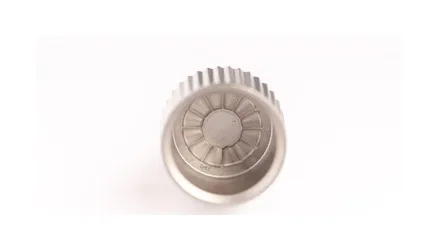
Useful for discussing integrated teeth, central drive features and compact near-net-shape geometry.
SINTS manufacturing reference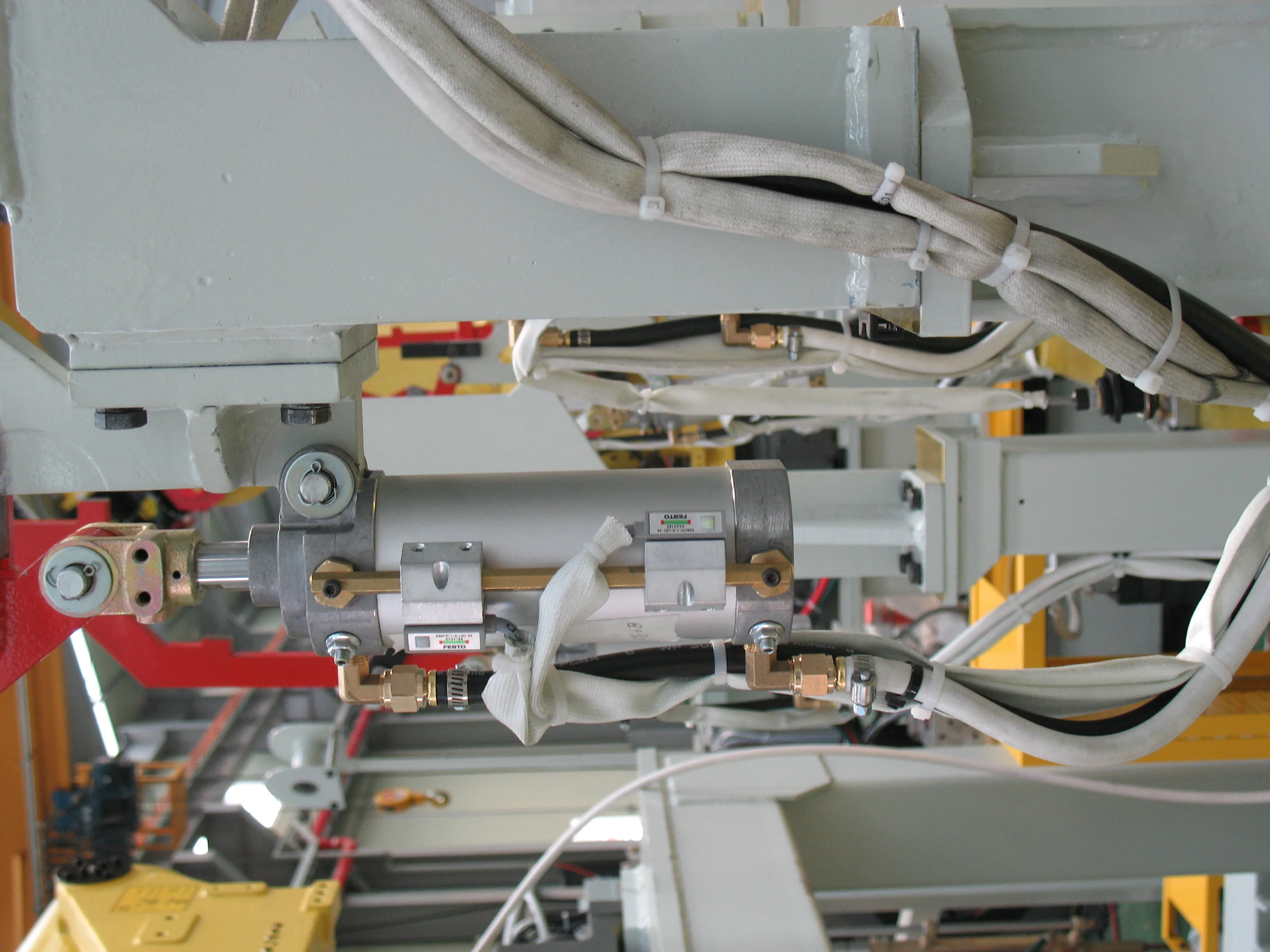
Useful for trigger, latch, carrier or guide discussions where cross-features, holes and wear interfaces matter.
SINTS manufacturing reference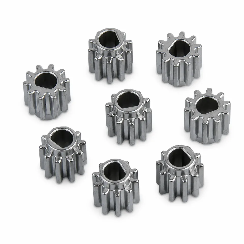
Relevant to cordless-drive discussions where tooth load, wear, noise, finishing and repeat-volume economics need review.
SINTS manufacturing referenceUse this page for impact, feed, valve, wear and safety context. Use Product family pages for the component-level manufacturing decision.
Trigger links, pawls, latches, cams, carriers and depth-adjuster parts.
Product family →Small gears, ratchets and drive components where tooth load, wear and finishing matter.
Product family →Valve-adjacent stems, seats and compact pneumatic-control parts where sealing surfaces need defined finishing.
Product family →Moving and locating interfaces where simple rotational geometry may still favor turning or grinding.
Product family →Jaws, nose inserts and high-contact parts where hardness, fatigue and edge/contact integrity dominate.
Product family →Small complex links, pawls, latches, adjusters, compact valve or riveter components where several machined features can be molded together.
Repeat-volume gears and structural drive parts with press-compatible geometry where density and tooth/loading requirements can be qualified.
Driver blades, long magazines, large cylinders, springs, seals and simple turned parts where stamping, extrusion, forming or turning are more natural.
Include functional datums, wear faces, bores and any known finishing operations.
State the current grade, heat treatment and surface requirements if already defined.
Series volume determines whether MIM/PM tooling can replace machining or assembled sub-features economically.
Share firing rate, expected life, impact direction or rivet pull load where relevant.
For jam- or wear-sensitive parts, include nail, staple or rivet size, material and feed format.
Tell us whether the pain point is wear, jamming, machining capacity, part count, cost, lead time or consistency.
Nailers, staplers and riveting tools convert stored energy into a single high-speed driving stroke. These answers cover the driver, linkage, magazine and jaw components that wear or jam, and how process route follows from the failure mode.
Small complex trigger links, pawls, latches, depth-adjuster parts, compact valve components and some nose-guide or drive-mechanism parts are worth evaluating first.
Usually not. Thin high-impact driver blades often fit stamping, machining and heat-treatment routes better. MIM is more useful around compact three-dimensional mechanism parts.
PM can be attractive for repeat-volume gears and compatible structural transmission parts, provided density, strength, tooth quality, noise and wear requirements are achievable.
Potentially, especially when the jaw or carrier is small and geometrically complex. Gripping teeth, hardness, wear, fatigue and dimensional stability must be qualified on the actual design.
It covers the parts that turn stored energy into one driving or setting stroke — driver blades, piston and cylinder interfaces, linkage and toggle parts, flywheel and roller components, magazine and feed hardware, rivet mandrel and jaw parts, and the small springs, retainers and pivots around them. The family spans nailers, staplers, riveters and cable or tie tools, which share high cycle counts but stress different surfaces.
Start from what fails. A part that wears on a sliding surface, fatigues at a stress concentration or deforms under impact points toward a different route than one whose cost is dominated by machining a complex profile. MIM suits small complex parts with integrated features and moderate loads, powder metallurgy suits repeat-volume structural and gear parts, and a tool steel with a specific heat treatment may remain the only sensible answer for the driver itself. Naming the failure mode first keeps the process discussion honest.
Usually not as a first move. A driver blade is a slender, impact-loaded part where edge condition, straightness and toughness matter, and those are easier to control by machining and heat treating from bar or plate. Near-net shaping becomes interesting when the geometry around the blade — a carrier, a guide or an integrated retention feature — is what drives cost, in which case the blade may stay machined while its carrier moves.
Send the drawing, the component's function in the stroke, the failure or cost driver you want addressed, the impact and cycle loads, the surface that wears, annual volume, the material or hardness of mating parts and any jam or misfire constraint. Those six inputs — function, failure mode, load, wear surface, volume and interface — are usually enough to say whether MIM, PM, machining or a conventional process is worth a detailed review.
We can review geometry, material, volume, wear/impact surfaces and likely secondary operations — including cases where stamping, turning or CNC remains the better route.