
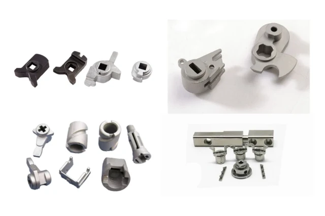
Locking and mechanism forms
Pivots, recesses and contact faces are reviewed with the mating hardware.
Discuss a similar component →Feature-rich links, cams, forks and locking elements for assemblies that transfer, guide or retain motion.
Pivots, recesses and contact faces are reviewed with the mating hardware.
Discuss a similar component →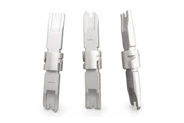
Cross-features and fork ends illustrate geometry that needs parting and secondary-operation review.
Discuss a similar component →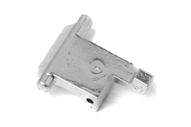
Identify the load direction and functional holes before choosing the route.
Discuss a similar component →Representative custom component references. Dimensions, material, manufacturing route and validation requirements are confirmed from your drawing; these are not off-the-shelf catalog items.
Pivoting or translating parts that transfer force between actuator, spring, jaw, latch or valve elements.
Compact locking or indexing parts where tooth/contact geometry, fatigue and wear determine durability.
Profiled parts that convert motion or generate force, often with critical contact surfaces that may need heat treatment or finishing.
Feature-rich components with holes, bosses, pockets, hooks or cross-features that can make MIM attractive at repeat volume.
| Review area | Information to define | Manufacturing decision |
|---|---|---|
| Load path | Peak load, direction, bending or impact events and the surrounding assembly. | Evaluate section transitions and material condition where stress concentrates. |
| Pivots & fits | Pin diameter, bore fit, bearing length, clearance and expected motion. | Plan reaming, sizing or machining where near-net geometry cannot satisfy the interface. |
| Contact & wear | Cam profile, latch engagement, sliding faces and the mating material. | Review local hardness, surface finish and geometry after heat treatment. |
| Cycle validation | Cycle target, failure modes, retention requirement and approval method. | Agree dimensional and functional sample checks before committing to production tooling. |
Material & final condition. MIM low-alloy or stainless grades may suit compact 3D geometry. The final choice depends on corrosion, fatigue, wear and heat treatment. Flat thin parts may be better reviewed as stamping or machining candidates. Review material data →
| Geometry / function | First route to evaluate | Why / watchout |
|---|---|---|
| Small 3D link / lever / latch | MIM — often a strong candidate | Integrated bosses, holes, hooks and thickness changes can replace several machining operations; fatigue and pivot/contact surfaces still need validation. |
| Cam / wedge with critical contact face | MIM + selective finishing, or CNC | Near-net geometry may be useful, but profile accuracy, hardness, surface condition and contact stress decide the final chain. |
| Press-friendly simple structural mechanism part | PM | Conventional PM can be efficient when features align with compaction direction and density/load targets are compatible. |
| Flat thin pawl / spring-like plate | Stamping / laser / machining | Simple sheet geometry usually should not be forced into MIM. |
| Low-volume or frequently revised mechanism | CNC / turning / fabrication | Tooling economics and design-change risk can outweigh near-net-shape savings. |
Mechanism DFM starts from the failure mode: bending, fatigue, impact, sliding wear, edge wear, pivot fretting or locking retention. Process choice follows the functional risk, not the part name.
Review geometry, material and volume, identify critical features and clarify the proposed tooling and secondary operations.
Define trial parts, dimensional checks, material confirmation and any customer-required functional approval.
Confirm the approved route, control plan, packaging and repeat-supply requirements for the program.
Links, wedges, cams, jaws and locking elements.
Application guide →Cams, wedges, latches, retainers and coupling mechanisms.
Application guide →Trigger links, pawls, latches, depth adjusters and ratchets.
Application guide →Levers, followers, cams and compact flow-control mechanisms.
Application guide →Include an assembly view, load direction, pivot/contact dimensions, cycle target, material/finish and annual quantity.