
Compact precision forms
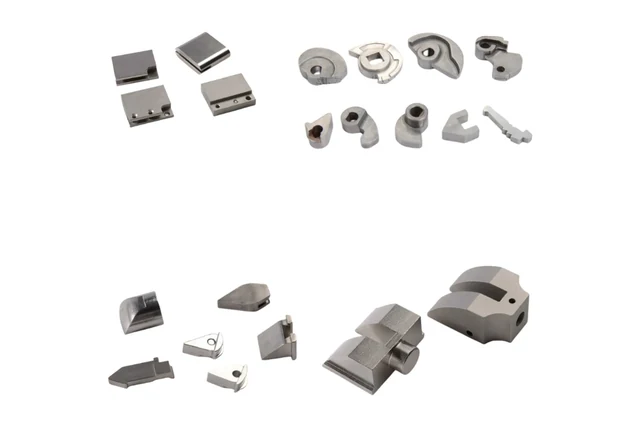
Locating faces, slots and mounting features illustrate different assembly requirements.
Discuss a similar component →Small custom metal parts with integrated mounting, locating and assembly features for OEM mechanisms.
Locating faces, slots and mounting features illustrate different assembly requirements.
Discuss a similar component →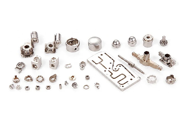
A selection of component shapes; exact grade, dimensions and finish follow the approved drawing.
Discuss a similar component →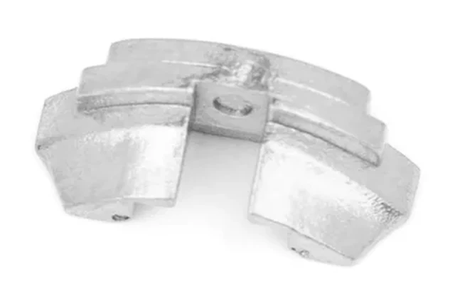
Review the critical faces and mating parts before deciding which features need machining.
Discuss a similar component →Representative custom component references. Dimensions, material, manufacturing route and validation requirements are confirmed from your drawing; these are not off-the-shelf catalog items.
Small structural interfaces with bosses, holes, hooks or pockets.
Compact rotating interfaces where pin fit, wear and cosmetic requirements can interact.
Small metal interfaces used to locate, join, retain or transfer load in an assembly.
Small enclosures or supports where MIM can consolidate geometry at repeat volume.
| Review area | Information to define | Manufacturing decision |
|---|---|---|
| Functional datums | Assembly references, mating surfaces, hole positions and tolerance stack-up. | Assign tight controls to functional features and identify the secondary-operation datums. |
| Wall transitions | Thin sections, ribs, bosses, pockets and thickness changes. | Review filling, shrinkage and distortion together with geometry consolidation. |
| Surface priorities | Cosmetic areas, contact faces, texture, coating and handling requirements. | Distinguish appearance requirements from functional roughness and fit. |
| Assembly verification | Joining method, engagement, clearance, handling and first-article expectations. | Agree how the component is checked in its intended assembly. |
Material & final condition. Stainless or low-alloy MIM grades may fit integrated 3D parts. The selection follows final properties, finish and assembly demands; dimensional precision comes from a defined process and inspection plan. Review material data →
| Component / condition | First route to evaluate | Why / watchout |
|---|---|---|
| Small 3D multi-feature part | MIM — often worth evaluating | Can consolidate machining operations when geometry is genuinely three-dimensional and repeat volume supports tooling. |
| Simple flat bracket | Stamping / laser / bending | Sheet geometry should usually remain in sheet processes. |
| Simple turned insert | Turning / CNC | Axisymmetric features normally favor machining unless other complexity changes the economics. |
| Press-friendly compact structural part | PM | Can be efficient where density/load and compaction direction fit the design. |
| Prototype / low-volume custom part | CNC / additive / fabrication | Avoid fixed tooling when geometry is not stable or volumes are low. |
Review geometry, material and volume, identify critical features and clarify the proposed tooling and secondary operations.
Define trial parts, dimensional checks, material confirmation and any customer-required functional approval.
Confirm the approved route, control plan, packaging and repeat-supply requirements for the program.
Compact guides, carriers, inserts and interfaces.
Application guide →Retainers, coupling-adjacent parts and compact interface hardware.
Application guide →Compact carriers, pivots and internal support parts.
Application guide →Small stainless inserts, carriers and service interfaces.
Application guide →Include assembly references, critical dimensions, appearance/finish zones, material target, program timing and annual quantity.