
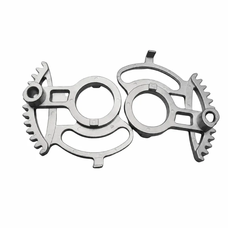
What a locking drive plate does against a mating profile
Review this component together with its mating parts and delivered condition. The interfaces below define the drawing information needed to assess forming, finishing and inspection.
This catalog entry concerns an internal mechanism part rather than a cut door key.
Central connection, working profile and angular-travel interfaces
Provide the central connection, working profile and angular travel.
Identify whether the part transmits rotation, indexes a position or locks another member.
Why distinguish an internal drive key from a door key?
The internal part is defined by its relationship to the mechanism, whereas an external key has a different scope and interface.
Naming the supplied component precisely avoids ambiguity over profiles, mating hardware and what the quotation actually includes.
Profile forming versus machining for engaging edges
Compare profile forming and machining with final control of engaging edges.
Functional profiles should not be rounded unintentionally during finishing.
The proposed route is confirmed for your drawing, material and quantity. An image does not establish a fixed tolerance or a complete process specification.
Compare manufacturing capabilities →Drive plates: three routes and the one condition that decides
This entry is an internal mechanism plate, not a cut door key. The distinction is not cosmetic: a door key is a cutter that mates with a cylinder, while a drive plate closes a dimensional chain inside the lock body. The two are made and inspected differently, so they should not be quoted against each other.
| Alternative process | When it wins on this part | What puts sintering back in front |
|---|---|---|
| Fine blanking | Wins on the flat plate whose outline is the function. One strike gives the full profile with a sheared edge clean enough to work against. | The plate then has one thickness everywhere. Any axial boss that has to seat in the lock body needs a separate turned part or a staking step, and that step becomes the weak link in the drive. |
| Stamping with heat treatment | Wins where the shape is simple and the requirement is strength rather than precision, since the hardening can follow the blanking. | Quenching distorts the working profile. If the profile is what transmits the torque, distortion has to be removed by grinding or coining, and both are per-piece costs that never amortise. |
| Wire EDM or laser cutting | Wins at prototype and on any irregular outline that would need an expensive die, with no tooling committed before the design settles. | Neither process produces a three-dimensional feature. A step in thickness, a chamfer that guides engagement, or a lug that stands off the plate all remain separate operations. |
| CNC milling | Wins on the thick plate with a step, where the step has to be square to the profile and both are referenced from one setup. | Milling a plate that is mostly a flat outline spends its time removing material that a die would never have added. That is fine for ten pieces and hard to defend for ten thousand. |
| Sintering | Wins where an axial boss, a radial locating lug and a change of thickness exist on one plate, because all three come out of the tool and the drive chain loses two joints. | It loses on the plain flat plate. There, blanking is faster to tool, cheaper per piece and needs no sizing step afterwards. |
Note. This table is a screening aid, not a recommendation against our own process. Where a row above describes your part better than the sintering route does, we will say so and quote against the route that actually fits; the quantities, alloy and tolerances on your drawing still decide the answer.
Before comparing prices, settle which part is being bought. A door key is judged on how it cuts and how it wears; a drive plate is judged on angular play in the assembled lock. A quotation that mixes the two is answering a question nobody asked.
Locking key material, treated-surface and corrosion requirements
Specify the base material, final condition and corrosion or appearance requirements.
Mark drive, guiding and contact surfaces that must meet their dimensions after treatment.
The component specification does not establish a security rating for the complete lock.
Review material-selection information →Engagement, orientation and mechanism-clearance checks
Check engagement, orientation and clearance against the mating mechanism.
Evaluate the agreed locking and release sequence.
Specify the drawing revision and the condition in which each dimension is inspected. Record the agreed dimensional and functional checks before sample approval.
Quality documentation →Prepare a Product-Specific RFQ
- Component definition. Send the 2D drawing and 3D model, where available, with the drawing revision and the requested part or assembly scope.
- Mating information. Include the assembly references needed to define the interfaces discussed above.
- Delivered condition. State material, finishing and inspection requirements, identifying any items that need a manufacturing recommendation.
- Supply plan. Include sample needs, expected order and annual quantities, packaging requirements and target timing.
Product Questions
Is this an externally cut key for a particular lock brand?
No. It is a custom internal drive-component reference; the required profile must come from the customer's drawing.
Why distinguish an internal drive key from a door key?
The internal part is defined by its relationship to the mechanism, whereas an external key has a different scope and interface. Naming the supplied component precisely avoids ambiguity over profiles, mating hardware and what the quotation actually includes.
How should the completed mechanism be checked?
Check engagement, orientation and clearance against the mating mechanism. Evaluate the agreed locking and release sequence.
Technical Context
The product-specific notes above identify drawing-review questions. General process and material references are collected separately; they do not verify a material grade, production qualification or performance claim for the pictured part.
Manufacturing and material references →