
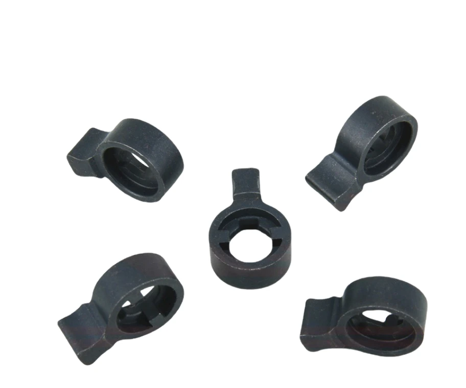
What door lock lever bushings support and connect
Review this component together with its mating parts and delivered condition. The interfaces below define the drawing information needed to assess forming, finishing and inspection.
The catalog reference shows several related profiles.
Central fit, projection orientation and mating-hardware interfaces
Define the central fit, projection orientation and mating lock hardware.
Relate the projection to the locating axis rather than dimensioning it from a free outer edge.
Why is projection orientation important on a lever bushing?
The projection engages another member at a position set by the central fit.
Its orientation links the bushing's location to the lock action.
Controlling only the circular fit can leave that engagement relationship unspecified.
PM, MIM and machining for ring and projection geometry
Compare PM, MIM and machining for the ring and projection geometry.
Working bores and contact faces may need secondary sizing or machining.
The proposed route is confirmed for your drawing, material and quantity. An image does not establish a fixed tolerance or a complete process specification.
Compare manufacturing capabilities →Lever bushing material, treated-surface and corrosion requirements
Specify the base material, final condition and corrosion or appearance requirements.
Mark drive, guiding and contact surfaces that must meet their dimensions after treatment.
The component specification does not establish a security rating for the complete lock.
Review material-selection information →Central fit, angular orientation and contact-clearance checks
Check central fit, angular orientation and contact clearance.
Verify operation after the specified final finish or treatment.
Specify the drawing revision and the condition in which each dimension is inspected. Record the agreed dimensional and functional checks before sample approval.
Quality documentation →Which dimensions move between lots on a sintered lever bushing
A first article shows what one lot can do. A repeat order asks a different question: whether the fifth lot still locates the lock hardware the way the first one did. On a lever bushing the answer rests on a small number of characteristics, and they do not all drift for the same reason.
| What drifts between lots | Where the drift comes from | What the release check catches |
|---|---|---|
| Centre bore size and cylindricity | The bore is usually sized or reamed after sintering, so its final size depends on how much material the sizing tool removes. Tool wear moves the bore in one direction across a production run, and a fresh tool starts at the other end of the allowance. | Pass a plug gauge at both ends of every run, and check the first and last parts on a CMM. The drawing should state the bore tolerance and the gauging condition rather than leaving the method to the supplier. |
| Angular position of the projection | The projection is oriented by an insert in the sizing tool. Insert wear and the way the part seats before pressing both shift that angle, and the shift is too small to see on the outside diameter. | Measure the angle from the centre axis on a fixture or a CMM, not from an outer edge. A drawing that dimensions the projection from a free outer surface cannot separate a true angular error from a diameter error. |
| Height from the seating face to the projection face | Fill weight is set by volume, and powder bulk density varies between lots. A small change in fill weight changes green density, and green density sets how much the part shrinks in the furnace. | Check the height against the seating face, not against the opposite end. State which face is the datum, because both faces are sized and either can be used to produce a passing reading. |
| Bore size after the surface treatment | Plating, passivation and black oxide all build or convert material, and the build inside a bore is not the same as on an exposed face. A bore at the top of its tolerance before coating can be tight after it. | Gauge after the final treatment, and write the dimension as measured in the delivered condition. Where the drawing specifies the size before coating, the drawing and the certificate will disagree at incoming inspection. |
| Surface hardness, where a hardened case is specified | Position in the furnace and quench severity vary across a load, so hardness readings scatter more than the drawing usually assumes. The scatter is largest on thin sections and at the ends of a load. | Use coupons that travel with the load plus a sample from the parts themselves, and state the test location and depth. A hardness value with no stated position cannot be defended when a customer re-checks the part. |
Note. This describes how the process behaves across a production run, not the history of any particular lot. Acceptance values, sample sizes and inspection methods come from the project drawing and the agreed quality plan.
The first three items can be closed out on the drawing, because a datum, a tolerance and a gauging condition are all things the drawing can state. The last two cannot: coating build and case depth are held by process control, and the only drawing-side defence is to specify the condition in which the part is measured.
Prepare a Product-Specific RFQ
- Component definition. Send the 2D drawing and 3D model, where available, with the drawing revision and the requested part or assembly scope.
- Mating information. Include the assembly references needed to define the interfaces discussed above.
- Delivered condition. State material, finishing and inspection requirements, identifying any items that need a manufacturing recommendation.
- Supply plan. Include sample needs, expected order and annual quantities, packaging requirements and target timing.
Product Questions
Which datum should locate a drive projection on a lock bushing?
Use the axis and assembly reference that control the bushing in the lock, with the required angular relationship defined explicitly.
Why is projection orientation important on a lever bushing?
The projection engages another member at a position set by the central fit. Its orientation links the bushing's location to the lock action. Controlling only the circular fit can leave that engagement relationship unspecified.
How should the completed mechanism be checked?
Check central fit, angular orientation and contact clearance. Verify operation after the specified final finish or treatment.
Technical Context
The product-specific notes above identify drawing-review questions. General process and material references are collected separately; they do not verify a material grade, production qualification or performance claim for the pictured part.
Manufacturing and material references →