
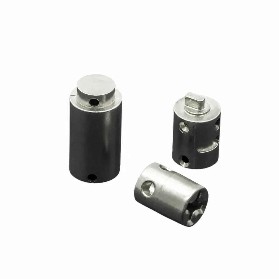
What packaging machine mechanism parts do in the cycle
Review this component together with its mating parts and delivered condition. The interfaces below define the drawing information needed to assess forming, finishing and inspection.
The catalog reference does not identify a complete machine or a universal replacement component.
Machine station, component function and mating-element interfaces
Specify the station, component function and mating elements.
Mark locating surfaces, openings and working contacts according to their role in the cycle.
Why specify the machine station as well as the part name?
The station explains the motion, neighboring components and environment the part must work with.
A broad packaging-machine label does not provide that context.
Identifying the location helps turn a generic reference into a component-specific engineering brief.
PM, MIM and machining for the actual profile
Compare PM, MIM and machining for the actual profile rather than choosing a process from a general product name.
Include any required finishing of working interfaces.
The proposed route is confirmed for your drawing, material and quantity. An image does not establish a fixed tolerance or a complete process specification.
Compare manufacturing capabilities →Packaging machinery: where powder metallurgy stops paying
Packaging lines have a particular demand shape: the machine lasts for years, each machine uses very few of each part, and the part is often needed again long after the machine stopped being built. That shape, more than geometry, decides the right process.
| Alternative process | When it wins on this part | What puts sintering back in front |
|---|---|---|
| CNC machining | Wins on the spare and repair part. Annual usage is often in single digits, so no tooling can be amortised no matter how complex the shape is. | Where the same part is designed into a new machine at real volume, the comparison changes. The same geometry that was milled for ten pieces can be formed for ten thousand. |
| Casting plus machining | Wins on the cam housing and the larger frame, where the section is heavy and the tolerance is moderate. | Every functional face still needs cutting afterwards. On a part whose value is a set of precise surfaces rather than its bulk, casting saves material and not time. |
| Forging plus machining | Wins on the linkage that takes shock during a jam. A jam is an impact event, and impact is where wrought material separates itself from sintered material. | Sintering is the better answer only where the load path is steady and the density can be specified and verified. That condition should be written down, not assumed. |
| Sheet metal fabrication | Wins on guards, brackets and rail mounts, which are flat, thin and mostly clearance. | Bent sheet gives one thickness and a soft edge. A cam or a pawl needs a hardened working face, and that is not something a bend can provide. |
| Powder metallurgy and sintering | Wins on cams, pawls, sprockets and guide blocks at stable volume, where the profile is formed in the tool and the part is small enough for the press. | It loses on the one-off repair part, and it loses on the heavy frame. Both are common in this industry, and both should be said in the first reply rather than after a quotation. |
Note. This table is a screening aid, not a recommendation against our own process. Where a row above describes your part better than the sintering route does, we will say so and quote against the route that actually fits; the quantities, alloy and tolerances on your drawing still decide the answer.
The honest recommendation for a packaging line is often a split: the wear parts formed in a tool, the spares cut from bar. Ask for that split explicitly. A single quotation covering both usually hides which half is carrying the cost.
Packaging mechanism material, wear treatment and environment requirements
Define material and final treatment against load direction, wear and the operating environment.
Mark surfaces whose fit or contact changes after finishing.
Rated loads, pressure limits and operating life require their own agreed design and acceptance requirements.
Review material-selection information →Locating relationship, motion clearance and wear-criteria checks
Check locating relationships, motion clearance and the customer's cycle or wear criteria.
State cleaning and environmental requirements for the installation.
Specify the drawing revision and the condition in which each dimension is inspected. Record the agreed dimensional and functional checks before sample approval.
Quality documentation →Prepare a Product-Specific RFQ
- Component definition. Send the 2D drawing and 3D model, where available, with the drawing revision and the requested part or assembly scope.
- Mating information. Include the assembly references needed to define the interfaces discussed above.
- Delivered condition. State material, finishing and inspection requirements, identifying any items that need a manufacturing recommendation.
- Supply plan. Include sample needs, expected order and annual quantities, packaging requirements and target timing.
Product Questions
Can a packaging-machine component be identified from its outline alone?
No. Its machine position, drawing revision and working interfaces are needed to establish the replacement or new-part requirements.
Why specify the machine station as well as the part name?
The station explains the motion, neighboring components and environment the part must work with. A broad packaging-machine label does not provide that context. Identifying the location helps turn a generic reference into a component-specific engineering brief.
How should the part be checked in the tool or mechanism?
Check locating relationships, motion clearance and the customer's cycle or wear criteria. State cleaning and environmental requirements for the installation.
Technical Context
The product-specific notes above identify drawing-review questions. General process and material references are collected separately; they do not verify a material grade, production qualification or performance claim for the pictured part.
Manufacturing and material references →