
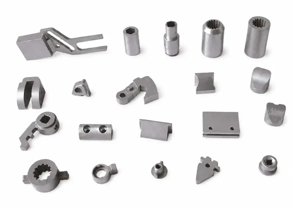
What a deadbolt does across its extension and retraction travel
Review this component together with its mating parts and delivered condition. The interfaces below define the drawing information needed to assess forming, finishing and inspection.
The group image is a broader geometry reference; the actual bolt requires an individual drawing.
Bolt profile, travel positions and guide interfaces
Define the bolt profile, extension and retraction positions, guide surfaces and connection to the actuator.
Identify which faces carry the locking contact.
Why define both extended and retracted positions?
The bolt must engage in one position and clear the surrounding mechanism in the other.
Its travel and support geometry connect those states.
Specifying only the engaged outline leaves the movement and clearance requirements incomplete.
Forming versus machining for deadbolt bodies
Compare forming and machining for the body and connecting features.
Critical guide or contact surfaces may need finishing in the final material condition.
The proposed route is confirmed for your drawing, material and quantity. An image does not establish a fixed tolerance or a complete process specification.
Compare manufacturing capabilities →Deadbolt material, treated-surface and corrosion requirements
Specify the base material, final condition and corrosion or appearance requirements.
Mark drive, guiding and contact surfaces that must meet their dimensions after treatment.
The component specification does not establish a security rating for the complete lock.
Review material-selection information →Deadbolt travel: two positions, one chain
A deadbolt is specified in two positions, and the chain has to close in both. That is where most of the difficulty comes from: a clearance that is right when extended is a different clearance when retracted.
| Link in the assembly chain | What it adds to the stack | Where to take it out of the chain |
|---|---|---|
| Extended and retracted positions | These two are the ends of the same chain, so tolerancing them independently allows a bolt that locks correctly and retracts short, or the reverse. | Dimension travel as one value between the two positions, then state the engagement depth separately. Two absolute positions do not guarantee the travel between them. |
| Guide surfaces | The guides hold the bolt on its path. Guide clearance appears as lateral play at the nose, which becomes a strike misalignment rather than a bolt problem. | Decide whether the guide is the float. If the design intends the bolt to find the strike, the guide clearance should be generous and stated; if not, it has to be held tightly and inspected as a pair. |
| Bolt profile at the nose | The nose shape determines how much misalignment the bolt can absorb before it jams. It is a functional shape, not an outline. | State the chamfer or radius at the nose with its own tolerance. It is the single feature that decides whether a strike that is slightly off still works. |
| Strike alignment | This link is in the door, not in the part, but it enters the same chain. Bolt position plus strike position plus door sag all add at the same point. | Agree the acceptable misalignment with the assembly, not with the part. A bolt held to a tight band cannot compensate for a strike that moves with the door. |
| Actuator connection | The connection to the mechanism carries the input travel. Any lost motion here is subtracted from the engagement depth without changing the bolt at all. | Specify engagement depth as the required outcome rather than as a bolt dimension. That puts the lost motion of the connection inside the requirement instead of outside it. |
Note. The links below describe how error accumulates in an assembly, not how to allocate tolerance for a specific drawing. Which link should carry the accumulation is a design decision that belongs to whoever owns the assembly; the supplier can only hold what the drawing names. Nothing here states an achievable tolerance for any dimension.
The practical test for a deadbolt drawing is whether it can be checked in one position. If every critical dimension can be measured with the bolt extended, the retracted end of the chain is being left to chance.
Travel, lock-body fit and strike-engagement checks
Inspect travel, fit in the lock body and engagement with the mating strike.
Any security or load requirement must be specified for the complete assembly.
Specify the drawing revision and the condition in which each dimension is inspected. Record the agreed dimensional and functional checks before sample approval.
Quality documentation →Prepare a Product-Specific RFQ
- Component definition. Send the 2D drawing and 3D model, where available, with the drawing revision and the requested part or assembly scope.
- Mating information. Include the assembly references needed to define the interfaces discussed above.
- Delivered condition. State material, finishing and inspection requirements, identifying any items that need a manufacturing recommendation.
- Supply plan. Include sample needs, expected order and annual quantities, packaging requirements and target timing.
Product Questions
Does this component page establish a security rating?
No. A rating belongs to a defined lock assembly and its qualification, not the component image.
Why define both extended and retracted positions?
The bolt must engage in one position and clear the surrounding mechanism in the other. Its travel and support geometry connect those states. Specifying only the engaged outline leaves the movement and clearance requirements incomplete.
How should the completed mechanism be checked?
Inspect travel, fit in the lock body and engagement with the mating strike. Any security or load requirement must be specified for the complete assembly.
Technical Context
The product-specific notes above identify drawing-review questions. General process and material references are collected separately; they do not verify a material grade, production qualification or performance claim for the pictured part.
Manufacturing and material references →