
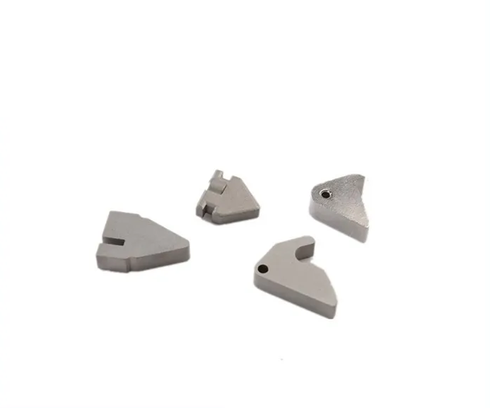
What a spring bolt does with its guide and return element
Review this component together with its mating parts and delivered condition. The interfaces below define the drawing information needed to assess forming, finishing and inspection.
Its angled contact face, guiding body and connection determine how it moves.
Guide, return element and actuator interfaces
Define the guide, return element and actuator relationship.
Specify travel, engagement and which faces contact the strike or mating part.
Why relate the latch face to the return arrangement?
The face engages the mating member while the guide and return mechanism control its movement.
Their relationship determines whether the latch reaches and leaves the required positions.
The drawing should describe that mechanism rather than treating the contact profile as an isolated shape.
MIM, PM and machining for latch profiles
Compare MIM, PM and machining for the latch profile and connection features.
Guide faces and holes may need final operations after forming.
The proposed route is confirmed for your drawing, material and quantity. An image does not establish a fixed tolerance or a complete process specification.
Compare manufacturing capabilities →Spring bolt material, treated-surface and corrosion requirements
Specify the base material, final condition and corrosion or appearance requirements.
Mark drive, guiding and contact surfaces that must meet their dimensions after treatment.
The component specification does not establish a security rating for the complete lock.
Review material-selection information →Guided motion, return and engagement checks
Check guided motion, return, engagement and any specified cycle test in the finished condition.
Include mating materials and surface requirements.
Specify the drawing revision and the condition in which each dimension is inspected. Record the agreed dimensional and functional checks before sample approval.
Quality documentation →What separates a spring bolt from a plain latch bar
A spring bolt carries its own return element, so the part has to deliver two functions at once: a sliding body that travels without binding, and a pocket that gives the spring a stable seat. Both are formed in the same body, which is why the review has to look at the spring pocket and the guide clearance together rather than as separate features.
| Feature | What it governs | How it is specified and verified |
|---|---|---|
| Spring pocket geometry | Preload and free travel of the bolt, and whether the latch re-seats after it is pushed back. | Pocket depth, width and floor radius called out on the 2D drawing; checked with pin gauges and on a sectioned first article. |
| Bolt-to-guide clearance | Whether the bolt slides without rattle and without stick-slip under a side load. | Clearance band at the guide interface; confirmed by a stroke test on the assembled lock, not on the loose part. |
| Nose profile and engagement depth | How the bolt meets the strike plate and how much of the nose actually carries the load. | Nose angle, engagement depth and edge break; verified against the mating strike geometry supplied with the RFQ. |
| Spring seat flatness and burr condition | Whether the spring loads evenly or rocks on a high spot and fatigues early. | Seat flatness and a burr-free requirement stated on the drawing; surface plate and visual check before assembly. |
| Finish on the sliding faces | Wear rate against the guide, and whether plating thickness closes the clearance. | Finish by zone rather than part-wide; sliding faces measured after plating so the clearance band still holds. |
Note. All dimensions and acceptance criteria are taken from the project drawing. The table lists the points that get reviewed; it does not fix values.
The route stops making sense where the bolt body is a simple constant section with no pocket and no guide feature. In that case a conventional powder metallurgy compact or a machined bar is cheaper, and the moulding cost of MIM buys nothing. It also stops making sense where the nose has to absorb impact in a thick, fully dense section, because the near-net body will not reach wrought density there.
Prepare a Product-Specific RFQ
- Component definition. Send the 2D drawing and 3D model, where available, with the drawing revision and the requested part or assembly scope.
- Mating information. Include the assembly references needed to define the interfaces discussed above.
- Delivered condition. State material, finishing and inspection requirements, identifying any items that need a manufacturing recommendation.
- Supply plan. Include sample needs, expected order and annual quantities, packaging requirements and target timing.
Product Questions
Can a spring bolt be assessed without the spring and guide arrangement?
The part can be measured alone, but return and engagement need the mating arrangement to be defined and tested.
Why relate the latch face to the return arrangement?
The face engages the mating member while the guide and return mechanism control its movement. Their relationship determines whether the latch reaches and leaves the required positions. The drawing should describe that mechanism rather than treating the contact profile as an isolated shape.
How should the completed mechanism be checked?
Check guided motion, return, engagement and any specified cycle test in the finished condition. Include mating materials and surface requirements.
Technical Context
The product-specific notes above identify drawing-review questions. General process and material references are collected separately; they do not verify a material grade, production qualification or performance claim for the pictured part.
Manufacturing and material references →