
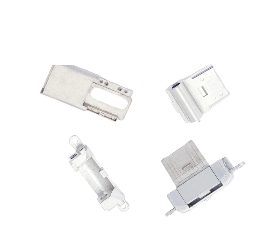
What lens mounting hardware provides around an optical assembly
Review this component together with its mating parts and delivered condition. The interfaces below define the drawing information needed to assess forming, finishing and inspection.
The reference includes several small forms with openings and support features.
Exact part, mating lens assembly and functional-datum interfaces
Specify the exact part, its mating lens assembly and the functional datums.
Do not use cosmetic outer contours as substitutes for alignment surfaces.
Why does a lens-related part need an exact supply definition?
A group photograph may show covers, supports or locating members with different roles.
The manufacturing requirements depend on which item is supplied and what it mates with.
An exact part boundary avoids treating an assembly reference as a single finished product.
MIM versus machining for integrated features and precision seats
Compare MIM and machining for integrated features and accessible precision seats.
The manufacturing plan should explain how the critical mounting relationships are established.
The proposed route is confirmed for your drawing, material and quantity. An image does not establish a fixed tolerance or a complete process specification.
Compare manufacturing capabilities →Which route suits lens mounting hardware
Most parts in this group are surfaces of revolution with one or two interruptions. That shape has cheap answers, which is why the honest comparison starts by asking what the part does that a turned or drawn part cannot.
| Alternative process | When it wins on this part | What puts sintering back in front |
|---|---|---|
| Deep drawing and stamping | Wins on caps, shrouds and thin rings. Wall thickness comes from the strip, so it is uniform along the whole height, and the per-piece cost is the lowest available. | Deep drawing cannot vary the wall thickness or add a locating boss on the rim without a second operation. Local thickening and formed seats are precisely what sintering gives in one cycle. |
| CNC turning | Wins on the bayonet ring and the retaining ring, where the thread and the seat are turned in one setup and the relationship between them is never re-established. | Forming a thread means cutting it afterwards, so the part pays for both. Turning only loses when the ring also needs non-turned features on its face or rim. |
| Aluminium extrusion plus machining | Wins on long sections with a constant profile, cut to length and finished at the ends. | Extrusion holds one cross-section and nothing along the length. Any change of section, or an end feature, brings back cutting and milling, which is where the saving disappears. |
| Die casting | Wins on the larger barrel or mount body, where the section is heavy enough to fill and mass is a disqualifier for sintering. | Draft on the seat is the problem: an optical seat that has to be square to the axis cannot carry a release angle, so the seat is machined afterwards and the casting only supplies the bulk. |
| Sintering | Wins where a bayonet lug, a locating slot and a spring seat have to coexist on one small ring, and each of the other routes above needs two or three setups to bring them together. | It loses as soon as the part is a plain ring. On a plain ring, turning is faster to quote, faster to make and has no tooling to amortise. |
Note. This table is a screening aid, not a recommendation against our own process. Where a row above describes your part better than the sintering route does, we will say so and quote against the route that actually fits; the quantities, alloy and tolerances on your drawing still decide the answer.
One instruction decides more than the process choice: whether a face that is polished is also a face that locates. Polishing rounds an edge, so any locating face needs its allowed stock stated explicitly. Left unstated, the finishing shop will treat it as cosmetic.
Lens hardware base material and finish requirements
Define base material, final condition and cosmetic finish separately.
Identify visible faces, permitted edge rounding and the dimensions that must be met after finishing.
Any magnetic, electrical or acoustic requirement needs its own specification.
Review material-selection information →Opening, locating-seat and attachment-feature checks
Inspect openings, locating seats and attachment features.
Any optical alignment or dust-protection requirement needs an assembly-level acceptance method.
Specify the drawing revision and the condition in which each dimension is inspected. Record the agreed dimensional and functional checks before sample approval.
Quality documentation →Prepare a Product-Specific RFQ
- Component definition. Send the 2D drawing and 3D model, where available, with the drawing revision and the requested part or assembly scope.
- Mating information. Include the assembly references needed to define the interfaces discussed above.
- Delivered condition. State material, finishing and inspection requirements, identifying any items that need a manufacturing recommendation.
- Supply plan. Include sample needs, expected order and annual quantities, packaging requirements and target timing.
Product Questions
Is the pictured hardware a complete lens cap or lens mount?
It is a component reference group. Identify the individual part and assembly scope in the inquiry.
Why does a lens-related part need an exact supply definition?
A group photograph may show covers, supports or locating members with different roles. The manufacturing requirements depend on which item is supplied and what it mates with. An exact part boundary avoids treating an assembly reference as a single finished product.
How are appearance and functional fit checked?
Inspect openings, locating seats and attachment features. Any optical alignment or dust-protection requirement needs an assembly-level acceptance method.
Technical Context
The product-specific notes above identify drawing-review questions. General process and material references are collected separately; they do not verify a material grade, production qualification or performance claim for the pictured part.
Manufacturing and material references →