
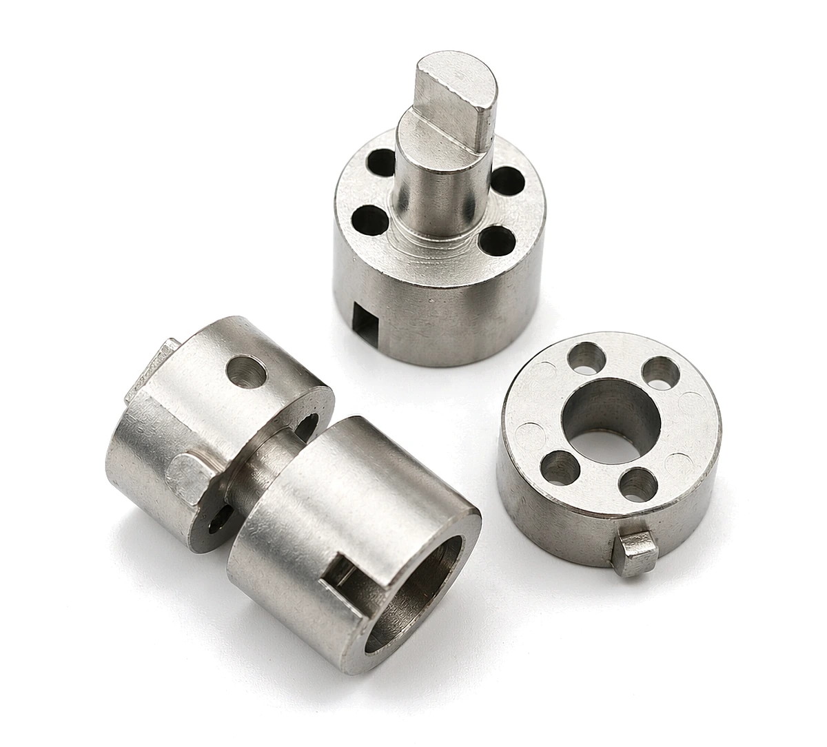
What a notebook spindle forms within the hinge axis
Review this component together with its mating parts and delivered condition. The interfaces below define the drawing information needed to assess forming, finishing and inspection.
Shaft-like and slotted reference forms illustrate why axis and retention details must be controlled together.
Journal, shoulder, retention and mating-bore interfaces
Define the journal, shoulders, drive or retention features and mating bore.
State which surfaces rotate and which remain fixed after assembly.
Why relate a shoulder to the spindle axis?
A shoulder may establish axial position while the journal establishes rotation or guidance.
Their relationship determines how the spindle sits in the mechanism.
Specifying them together is more useful than checking their dimensions without a shared assembly reference.
Turning and grinding versus MIM for spindle geometry
Compare turning and grinding for simple axes with MIM or other forming for integrated non-round features.
Final journal finishing may be independent of body production.
The proposed route is confirmed for your drawing, material and quantity. An image does not establish a fixed tolerance or a complete process specification.
Compare manufacturing capabilities →Notebook spindle material and finish requirements
Define base material, final condition and cosmetic finish separately.
Identify visible faces, permitted edge rounding and the dimensions that must be met after finishing.
Any magnetic, electrical or acoustic requirement needs its own specification.
Review material-selection information →Axis relationship, shoulder position and retention-fit checks
Inspect axis relationships, shoulder position and retention fit.
Evaluate movement with the actual mating hinge components and finish condition.
Specify the drawing revision and the condition in which each dimension is inspected. Record the agreed dimensional and functional checks before sample approval.
Quality documentation →What a notebook spindle fails on, and why most of it is a datum question
A lid spindle is a short shaft supported at both ends, and that constraint decides which failures are possible. Almost every one of them traces back to which face the drawing treats as the axis, and to whether the fit was specified in the free state or in the installed state.
| What goes wrong in service | What drives it | Where the drawing closes it out |
|---|---|---|
| The lid wobbles at the open position | Support length is the real variable, not diameter. A spindle that is only located over a short length at each end will let the lid rock however good the bore fit is, and the user experiences it as a loose hinge rather than a loose shaft. | Journal length and the bore fit stated as a pair, plus the effective support span on the assembly drawing; verified by measuring angular play at the lid edge with the spindle installed, not by gauging the shaft alone. |
| Black debris and a stain appear at the shoulder | If the shoulder face is not square to the axis, the face touches the mating part on one edge only. The resulting micro-motion frets the contact and produces exactly the dark residue users report as wear. | Squareness of the shoulder face to the journal axis, called out on the face that carries the load; verified by blue-checking the shoulder against a mating part on a sample, in addition to the CMM squareness value. |
| The hinge stiffens after a warm soak | Clearance is usually sized at room temperature, then the device runs warm or sits in a car. A steel spindle in an aluminium or zinc bracket loses clearance as it heats, and the same fit that was free on the bench becomes an interference. | The fit specified at the service temperature the product is qualified for, with the mating material named on the drawing; verified by measuring opening torque after a soak at the qualification temperature rather than cold. |
| The spindle walks out of the bracket | Retention is often a groove or a staked end, and both live at the thinnest section of the part. A groove with no root radius concentrates load exactly where the material has least to give. | Groove position, depth and root radius called out individually, plus the retention method and the axial load it must resist; verified by an axial push-out test on the assembled hinge. |
| The shaft bends at the step | The step between the journal and the body is the stiffness change, and grinding undercuts put a sharp corner exactly there. A bend that starts at the step looks like a bent spindle but is a radius problem. | Transition radius at the step, and an explicit statement that no undercut is permitted without approval; verified by sectioning and by a bend test with the load applied beyond the step. |
Note. The table names service failure modes and the drawing features that address them; it sets no acceptance values. Dimensions, tolerances and test criteria come from the project drawing.
Four of the five items are drawing problems in the strict sense: support span, shoulder squareness, retention geometry and the step radius are all decided before a chip is cut, and none of them are improved by holding a tighter diameter. The thermal item is different, because it is a specification problem rather than a manufacturing one: the clearance can be perfectly made and still wrong, if it was sized at the wrong temperature with the wrong mating material. That is the item worth settling in the RFQ rather than in the quality report.
Prepare a Product-Specific RFQ
- Component definition. Send the 2D drawing and 3D model, where available, with the drawing revision and the requested part or assembly scope.
- Mating information. Include the assembly references needed to define the interfaces discussed above.
- Delivered condition. State material, finishing and inspection requirements, identifying any items that need a manufacturing recommendation.
- Supply plan. Include sample needs, expected order and annual quantities, packaging requirements and target timing.
Product Questions
When is a turned spindle preferable to an integrated formed part?
A simple rotational profile often merits a turning comparison; added non-round features and quantity may change the route assessment.
Why relate a shoulder to the spindle axis?
A shoulder may establish axial position while the journal establishes rotation or guidance. Their relationship determines how the spindle sits in the mechanism. Specifying them together is more useful than checking their dimensions without a shared assembly reference.
How are appearance and functional fit checked?
Inspect axis relationships, shoulder position and retention fit. Evaluate movement with the actual mating hinge components and finish condition.
Technical Context
The product-specific notes above identify drawing-review questions. General process and material references are collected separately; they do not verify a material grade, production qualification or performance claim for the pictured part.
Manufacturing and material references →