
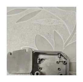
What a headset hinge does between moving device sections
Review this component together with its mating parts and delivered condition. The interfaces below define the drawing information needed to assess forming, finishing and inspection.
A quotation should identify the metal hinge component rather than assume supply of a complete headset mechanism.
Pivot, stop location and shell-attachment interfaces
Define the pivot, stop locations and attachment to the shell.
Distinguish cosmetic faces from bearing or contact surfaces, including clearances after finishing.
Why separate hinge location from friction elements?
The hinge bracket establishes position, while other members may provide friction or preload.
Combining those requirements into a single vague feel specification makes component approval difficult.
Define the bracket interfaces and the assembled operating test as related but separate requirements.
MIM versus machining for integrated hinge features
Review integrated hinge features for MIM or machining against the actual wall geometry.
Pin bores and contact surfaces may need secondary finishing or a separate pin.
The proposed route is confirmed for your drawing, material and quantity. An image does not establish a fixed tolerance or a complete process specification.
Compare manufacturing capabilities →Hinge base material, cosmetic finish and motion requirements
Define base material, final condition and cosmetic finish separately.
Identify visible faces, permitted edge rounding and the dimensions that must be met after finishing.
Any magnetic, electrical or acoustic requirement needs its own specification.
Review material-selection information →Pivot alignment, shell fit and movement-range checks
Check pivot alignment, shell fit, movement range and the agreed operating feel.
Cycle evaluation must use the actual mating parts and customer requirements.
Specify the drawing revision and the condition in which each dimension is inspected. Record the agreed dimensional and functional checks before sample approval.
Quality documentation →How headset hinges fail in the field, and what the drawing has to pin down
A headset hinge is a small part asked to do three things at once: hold a position, resist being closed, and survive being dropped from ear height onto a hard floor. The failures below are the ones that come back from users rather than from the inspection bench, which is why they are rarely visible on a first-article report.
| What goes wrong in service | What drives it | Where the drawing closes it out |
|---|---|---|
| The detent click softens after a few months of use | The detent is a rubbing pair, not a spring. If the bump is formed in the same body as the arm and never gets a defined contact band, load sits on a line rather than an area, and the arm wears a groove into its own detent. Plating on both members makes it worse because the softer coat goes first. | Bump height and crown radius with a tolerance band on the assembled breakaway torque, not on the loose part; verified on a cycling fixture that records torque at the start, middle and end of the run, at the temperature the product is sold for. |
| An arm cracks at the screw boss | Two things stack here: boss wall thickness against thread engagement, and the corner where the boss meets the arm web, which acts as a stress riser. Sintered material at that inner corner is the least forgiving area of the part. | Boss outside diameter, minimum wall and root fillet radius called out separately; verified by sectioning a first article through the boss and by a torque-to-failure test at the specified screw size rather than a generic pull test. |
| The hinge binds after the headset is dropped | The two arms deflect by different amounts on impact, so the pivot bores stop being parallel. A bore fit that was correct when concentric now pinches at one end, and the user reads it as a stiff hinge. | Arm thickness and rib layout, plus a parallelism callout between the two pivot bores at assembly level; verified by dropping a sample build and re-measuring opening torque rather than by inspecting the part as delivered. |
| Cosmetic pits appear once the visible face is polished | Polishing removes the dense as-sintered skin and opens the pores underneath. The pits were not created by polishing; the polishing allowance simply decided how deep they show. | Which faces are polished, how much stock the polish removes, and a cosmetic zone definition that separates the visible flank from the hidden inner face; verified by polishing a sample charge through to final finish, never on the raw part. |
| Play develops at the pivot pin | The pin and the bore are usually chosen at nominal, then only one of the two gets a coating. Thickness on one member closes a fit that was designed as a clearance, and the mismatch shows up as rattle long before anything wears. | Fit conditioned on the post-coating state, plus the pin material and hardness as a paired requirement; verified after coating with the production pin, not with a gauge pin at nominal size. |
Note. The table names service failure modes and the drawing features that address them; it sets no acceptance values. Dimensions, tolerances and test criteria come from the project drawing.
Splitting this list is more useful than prioritising it. The boss crack, the binding arm and the pivot play are drawing problems: no amount of process control rescues a wall that is too thin or a fit specified in the wrong condition. The detent decay and the polished-flank pitting are process problems, and they respond to tool maintenance and to how much stock the polish is allowed to take. A hinge that fails on the first group cannot be fixed by tightening inspection, and one that fails on the second cannot be fixed by changing the tolerance.
Prepare a Product-Specific RFQ
- Component definition. Send the 2D drawing and 3D model, where available, with the drawing revision and the requested part or assembly scope.
- Mating information. Include the assembly references needed to define the interfaces discussed above.
- Delivered condition. State material, finishing and inspection requirements, identifying any items that need a manufacturing recommendation.
- Supply plan. Include sample needs, expected order and annual quantities, packaging requirements and target timing.
Product Questions
Does the metal hinge alone determine opening torque?
No. Pins, friction elements, finish and assembly all contribute; provide the complete hinge arrangement and desired test method.
Why separate hinge location from friction elements?
The hinge bracket establishes position, while other members may provide friction or preload. Combining those requirements into a single vague feel specification makes component approval difficult. Define the bracket interfaces and the assembled operating test as related but separate requirements.
How are appearance and functional fit checked?
Check pivot alignment, shell fit, movement range and the agreed operating feel. Cycle evaluation must use the actual mating parts and customer requirements.
Technical Context
The product-specific notes above identify drawing-review questions. General process and material references are collected separately; they do not verify a material grade, production qualification or performance claim for the pictured part.
Manufacturing and material references →