Manufacturing Capabilities

Multiple Manufacturing Routes, One Engineering Review

SINTS compares metal injection molding, conventional powder metallurgy, gear manufacturing, CNC finishing and secondary operations from the same engineering brief. Geometry, material, annual volume, critical interfaces and final-part requirements determine the route before tooling is fixed.

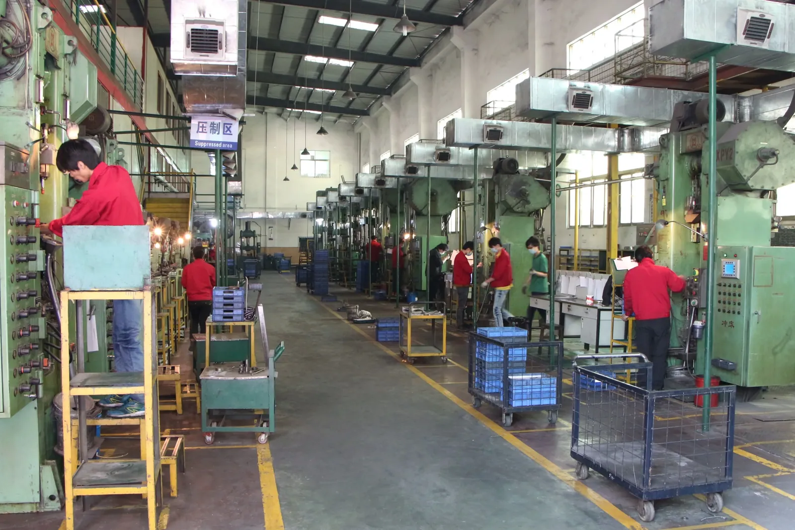
Metal injection molding production line at SINTS Zhongshan
1995
Manufacturing Since
2
Manufacturing Bases
45,000
m² Combined Manufacturing Area
IATF
16949 PM Scope
DFM
Project-Specific Review
Process Portfolio

Choose the process that fits the part

We do not force every job into one technology. The drawing, annual demand and functional risks decide which route should remain simple, which features can be consolidated, and where secondary control is worth paying for. For a broader comparison beyond the core SINTS routes, see 9 metal manufacturing processes.

01

Metal Injection Molding

Complex 3D geometry, thin walls, undercuts and side features where molded geometry and repeat production justify tooling.

Complex geometry · repeat production
02

Powder Metallurgy

Press-and-sinter production for gears, bushings, cams and structural components suited to uniaxial compaction.

Gears · bushings · structural parts
03

Gear Manufacturing & Finishing

PM, MIM and conventional gear-cutting or finishing routes are compared according to tooth geometry, load, accuracy, runout, heat treatment and annual volume.

Tooth form · load · accuracy · finishing
04

CNC Finishing

Turning, milling, grinding and tapping for critical features that require secondary dimensional or surface control.

Critical features · secondary finishing
05

Heat Treatment

Heat-treatment routes are selected according to alloy, hardness, wear and customer specification.

Selected to alloy & specification
06

Surface & Assembly

Surface treatment, marking and assembly support are selected according to drawing and program requirements.

Per drawing & project

Prefer to start from the component instead of the process?

Browse the eight product categories by function, or send the drawing and let engineering compare the practical routes for you.

Process 01

Metal Injection Molding (MIM)

MIM uses fine metal powder mixed with a binder, injection molding, debinding and sintering to create compact three-dimensional metal components. Its value comes from geometry consolidation and repeat production—not from being a universal replacement for machining.

MIM is evaluated when the part has enough 3D complexity and repeat demand to justify tooling. The economic crossover depends on the drawing, material, secondary operations, validation scope and forecast volume, so SINTS does not publish one universal minimum or “best” annual quantity.

MIM review itemHow SINTS evaluates it
Geometry3D complexity, wall transitions, gates/parting lines, shrinkage and distortion risk are reviewed from the drawing.
Critical dimensionsAs-sintered capability and any required machining/grinding are confirmed feature by feature.
MaterialDocumented grades and project-specific materials are checked against strength, corrosion, wear and finishing requirements.
Tooling / MOQ / timingQuoted from part geometry, alloy, annual volume and validation requirements.
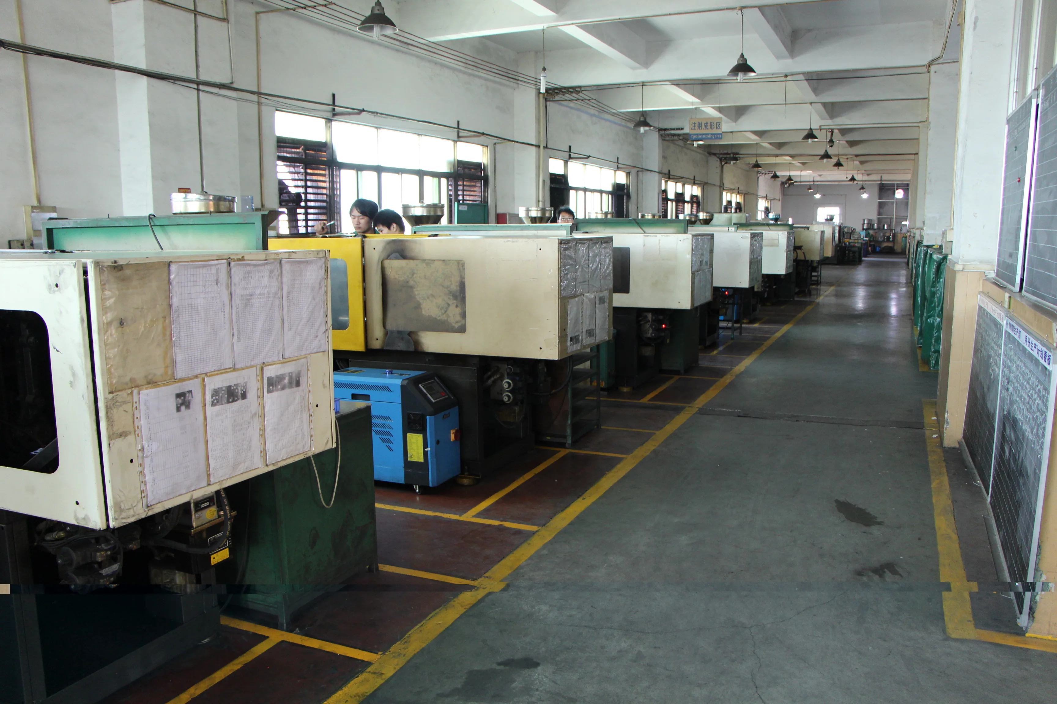
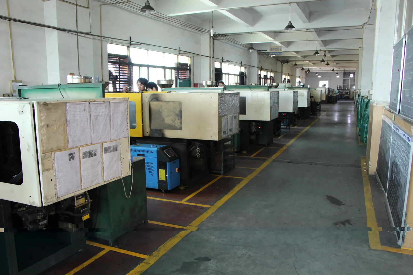
MIM injection presses running production at SINTS
Process 02

Conventional Powder Metallurgy (PM)

SINTS supports press-and-sinter powder metallurgy for gears, bushings, cams and structural parts. Press direction, density distribution, tooling geometry, heat treatment and secondary finishing are reviewed from the drawing before PM is recommended.

PM is strongest when the part can be compacted along a practical pressing direction and the required density, tooth or bearing surfaces, heat treatment and post-sinter operations remain compatible with the functional requirement.

PM review itemHow SINTS evaluates it
Compaction geometryPress direction, wall/step geometry and density distribution are checked before PM is recommended.
Functional surfacesBores, faces, teeth and datums are reviewed for sizing, machining, grinding or as-sintered control.
Material / densityAlloy, density/porosity and heat-treatment requirements are tied to the final application.
Tooling / MOQ / timingConfirmed per drawing and forecast volume after the manufacturing route is selected.
Continuous sintering furnace line at SINTS
Tolerance Capability

What we hold — and what it takes to hold it

Tighter control can add tooling, secondary machining or inspection steps. The drawing should identify which dimensions are truly functional so SINTS can propose the most economical control route.

FeatureEngineering reviewPossible control route
Linear dimensionsShrinkage, tool condition, datum scheme and tolerance stack are reviewed from the drawing.As-sintered where practical; machining/grinding where required.
Bores & mating fitsFit, concentricity and functional clearance determine the control plan.Sizing, reaming, machining or grinding as needed.
Flatness / runoutPart geometry, support during sintering and mating function are evaluated together.Process optimization plus secondary finishing when necessary.
Surface conditionWear, sealing, cosmetic and coating requirements are confirmed per surface.As-sintered, tumbling, polishing, machining, coating or other agreed finish.

Drawing tolerances, datum schemes and geometric callouts are reviewed feature by feature. SINTS does not publish one universal tolerance or cost premium for every MIM/PM geometry.

Secondary Operations

Finished parts, Not blanks

Secondary operations are planned as part of the manufacturing route. Depending on the process and project, work may use SINTS in-house equipment or qualified supporting resources under the same project and quality requirements.

01

Vacuum Heat Treatment

Heat-treatment options are selected according to alloy, drawing and required properties; the applicable route is confirmed during quotation.

02

CNC Machining

Turning, milling, drilling, tapping and grinding on sintered blanks. Used where tolerance, thread quality or a sealing face demands it.

03

Surface Finishing

Tumbling, blasting, passivation, polishing and other finishing routes can be reviewed according to edge, surface and cosmetic requirements.

04

Coating & Plating

Plating and coating options are selected according to corrosion, wear, appearance and customer compliance requirements.

05

Laser Marking

Part numbers, lot codes, logos and datamatrix directly on the component for traceability programs.

06

Sub-Assembly

Riveting, pressing, staking, spring and pin insertion, threaded insert fitting, packaging to customer artwork.

07

Dedicated Inspection Cells

Optical sorting, gauges and manual inspection can be applied to characteristics defined in the customer control plan.

08

Export Packing

Packing method is agreed according to part protection, shipment mode, destination and customer packaging requirements.

From Drawing to Shipment

The route your part takes

DFM Review

Engineers review geometry, wall sections, datums, material, functional features and process fit. Feedback timing is confirmed with the project quotation.

Tooling & Trial

Tool design, steel cutting, T0 trial. Dimensional report on first shots before any production commitment.

First Article

First-article inspection and approval documentation are prepared according to the agreed validation plan; PPAP content is supplied when required by the customer program.

Series Production

Production follows the agreed control plan, with critical-characteristic inspection, traceability and shipment documentation matched to the customer program.

Equipment

The machines behind the numbers

MIM injection molding machines at SINTS

MIM Injection Lines

Dedicated metal feedstock injection presses with closed-loop process monitoring and automatic part handling.

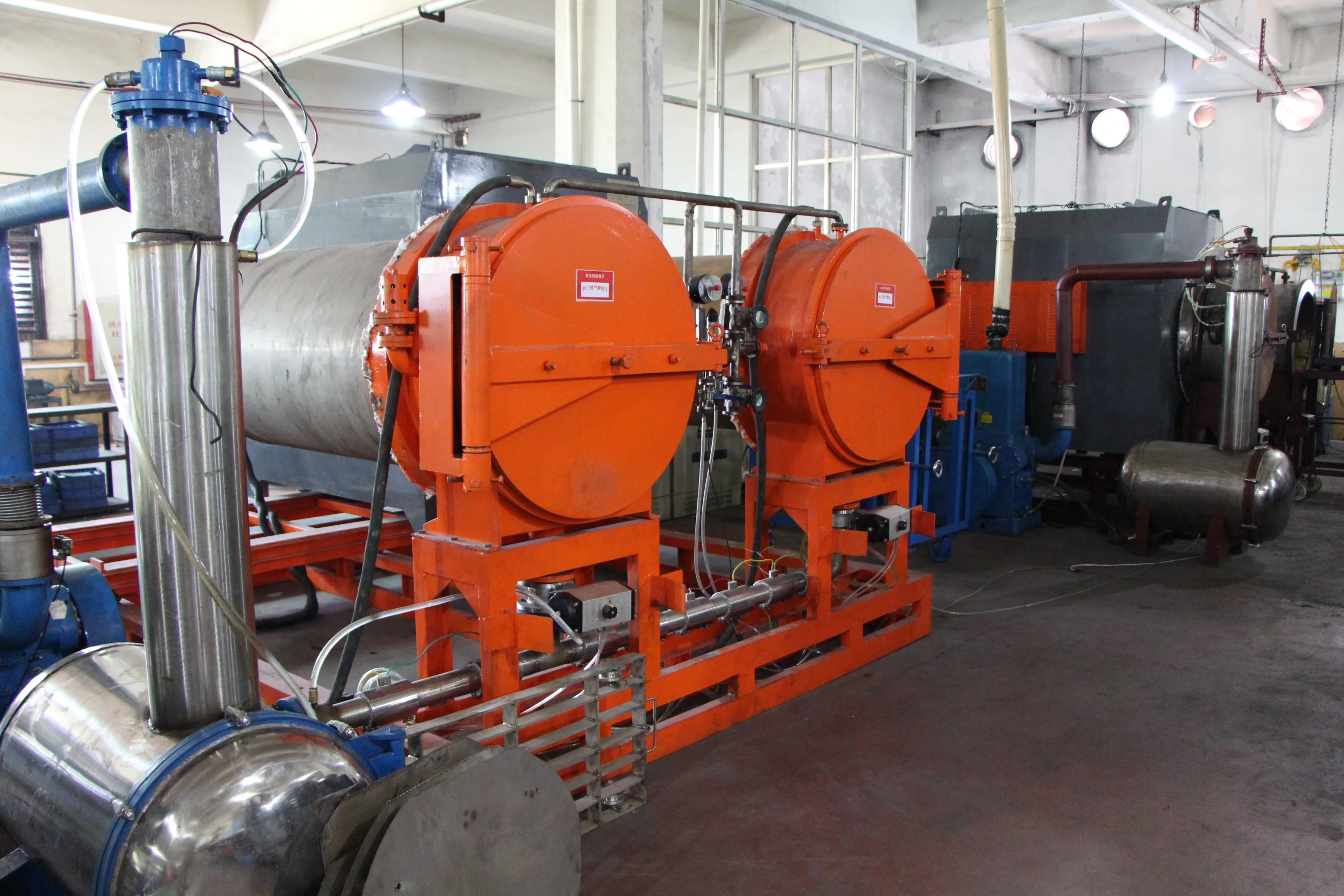
Vacuum sintering furnaces at SINTS

Vacuum & Continuous Furnaces

Vacuum and controlled-atmosphere sintering resources support PM and MIM programs, with thermal profiles and production records managed according to the applicable process plan.

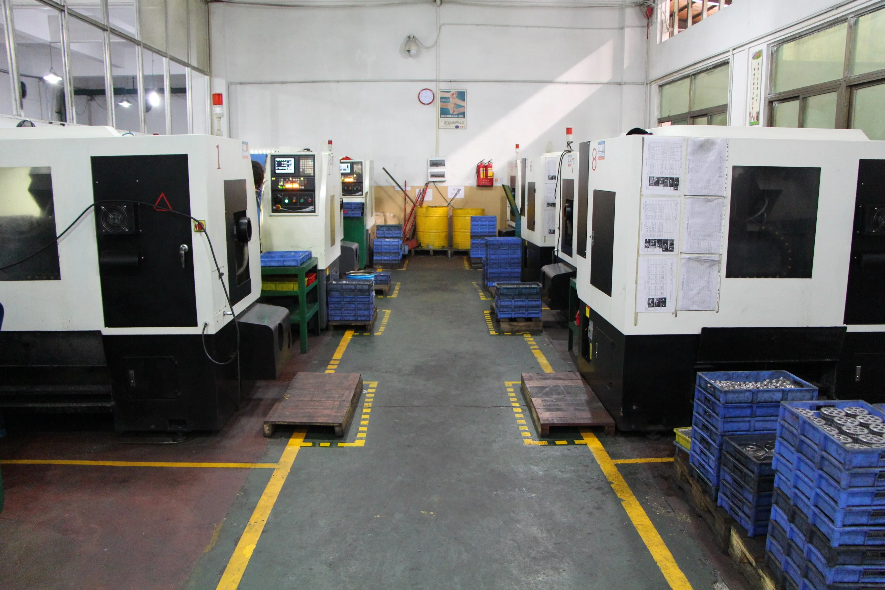
CNC machining centres at SINTS

CNC Machining Centres

Turning centres, 3-axis and 4-axis mills, centreless and surface grinders for post-sinter operations.

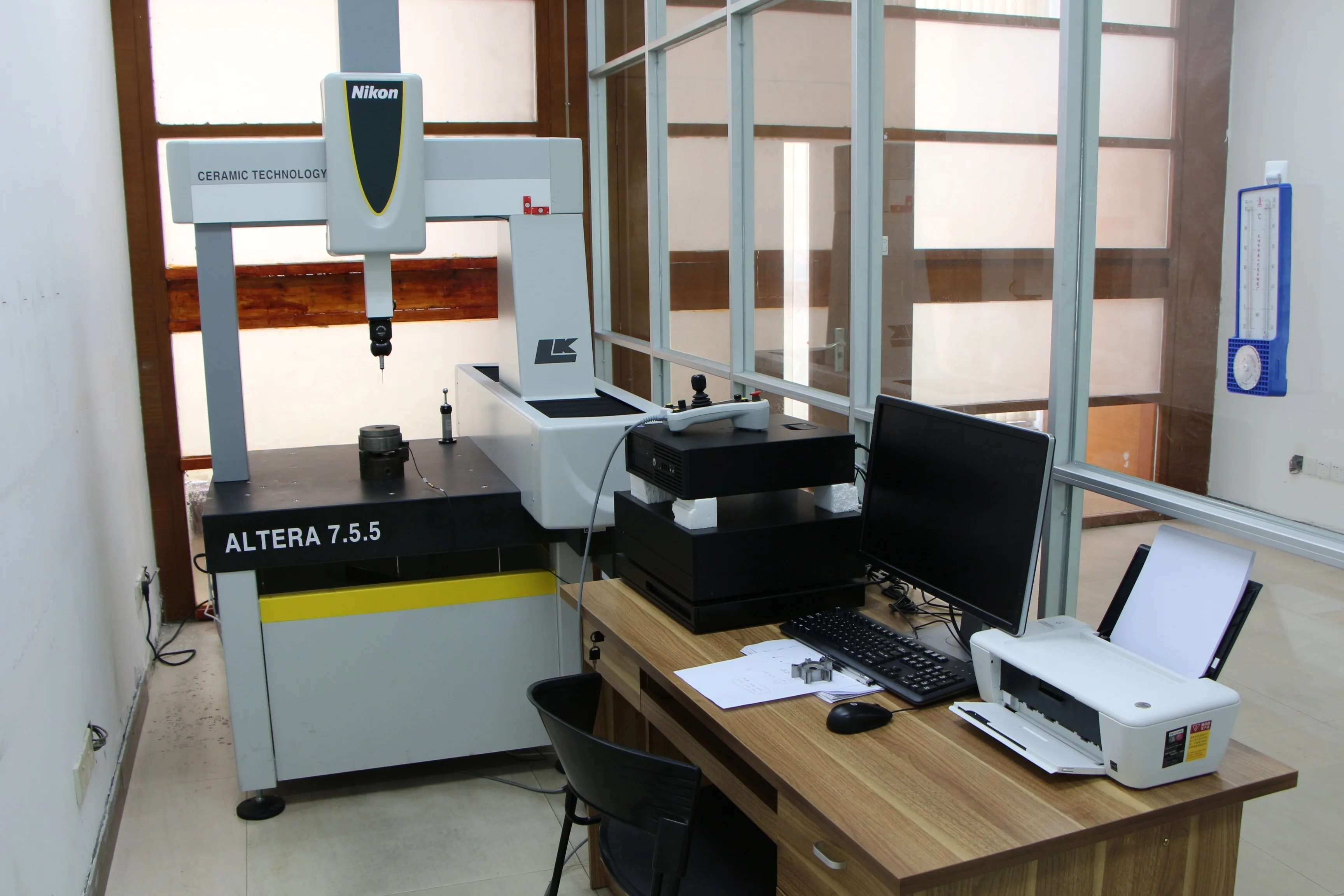
Coordinate measuring machine in the SINTS metrology lab

Metrology Lab

CMM, optical comparators, roughness testers, hardness testers, density apparatus and metallographic preparation.

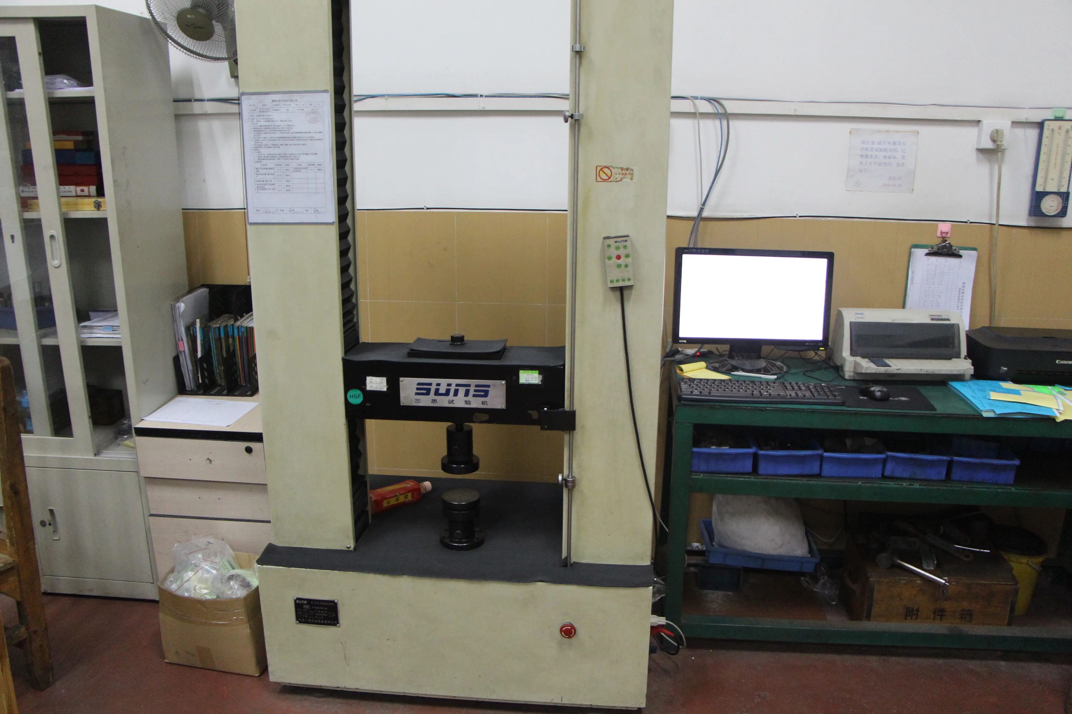
Universal testing machine for tensile testing at SINTS

Mechanical Testing

Universal testing machine for tensile and yield verification per ISO 6892, plus impact and fatigue sampling.

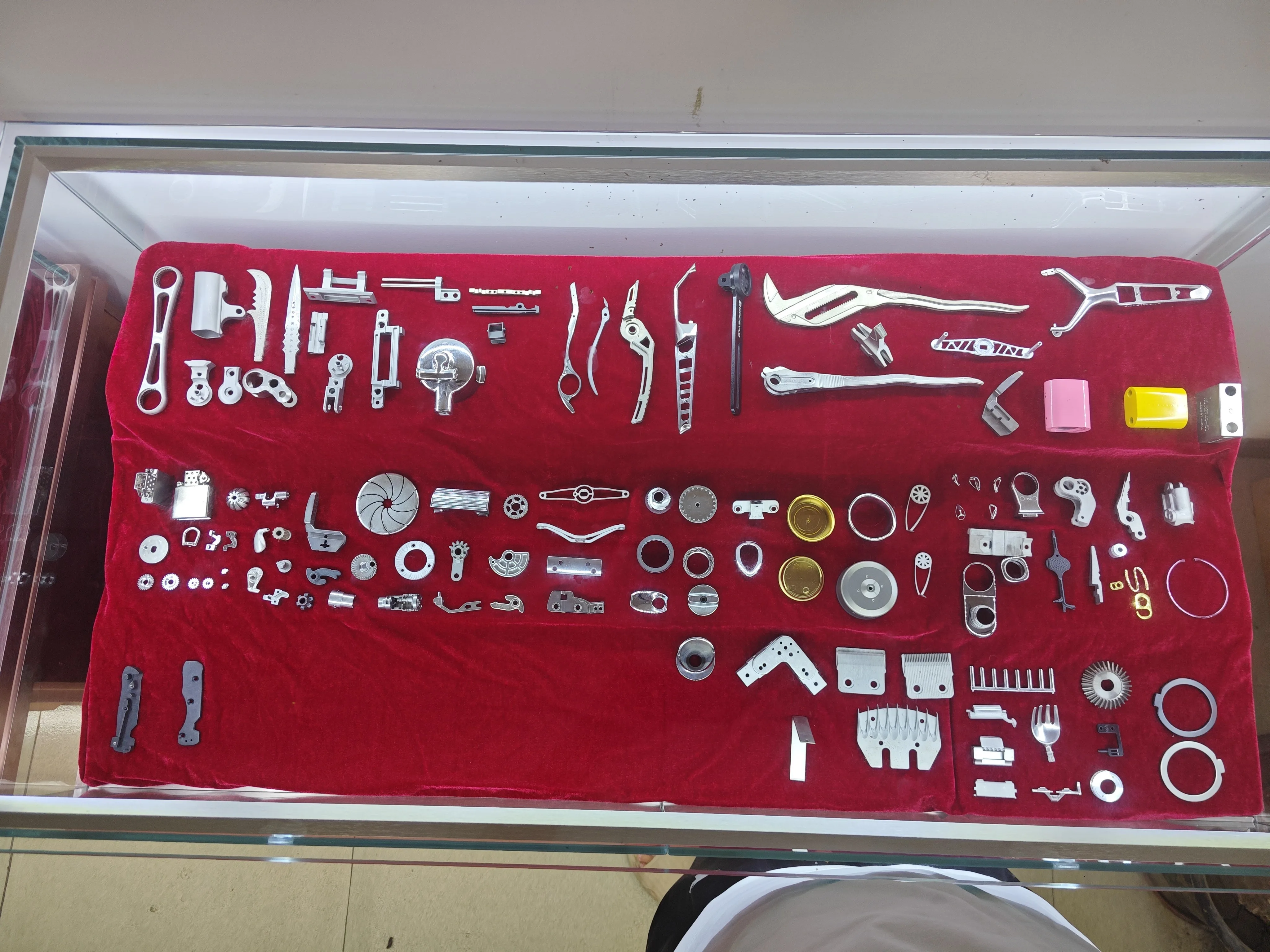
Reference parts library at SINTS showroom

Reference Part Library

Physical production references are maintained for engineering discussion. Similar geometry can inform DFM, but capability is confirmed from the new drawing.

Engineering FAQ

Questions buyers ask before tooling

What part size can SINTS produce with MIM?

MIM size suitability depends on geometry, wall sections, material, flow length, distortion risk and required properties. Send the drawing and SINTS will confirm whether MIM is practical or whether another route is better.

What tolerances can you hold as-sintered?

As-sintered tolerance depends on material, geometry, feature location, shrinkage and datum strategy. Critical dimensions are reviewed individually, with sizing, machining or grinding added where required.

What is your minimum order quantity?

MOQ is project-specific. Tooling economics, part geometry, material, annual demand and validation requirements are reviewed before a production MOQ is proposed.

Do you provide secondary operations?

Yes. SINTS can support heat treatment, CNC, grinding, tapping, tumbling, passivation, plating, PVD, laser marking and sub-assembly. The exact route and whether an operation is in-house or supported by a qualified resource are confirmed during quotation.

How long does tooling take?

Tooling and first-article timing depend on geometry, mold complexity, material and validation scope. A project schedule is provided after DFM and drawing review.

Can you match a part currently made by machining or casting?

Potential conversions are reviewed from the drawing, material, current process, annual demand and required performance. SINTS compares tooling and unit economics before recommending MIM, PM, CNC or a hybrid route.

Send a drawing. Start with a manufacturability review.

STEP, IGES, X_T or a dimensioned PDF is enough to start. SINTS will review process fit, critical tolerances, material, tooling considerations and the information needed for a quotation.

Frequently Asked Questions

Practical answers for OEM sourcing and engineering teams.

What manufacturing processes does SINTS offer?

SINTS supports metal injection molding (MIM), powder metallurgy, gear programs, CNC finishing, heat treatment and surface finishing. The recommended route depends on the drawing, material, annual volume, tolerances and application.

What are SINTS's MIM tolerances?

There is no single tolerance that applies to every MIM feature. SINTS reviews shrinkage, geometry, datums and functional fits, then identifies which dimensions can remain as-sintered and which need secondary control.

What is the largest part SINTS can make by MIM?

Maximum practical MIM size depends on geometry, material, wall thickness, flow length and distortion risk rather than weight alone. Larger or simpler parts may be better suited to PM, machining or another route.

What production volume does MIM suit best?

MIM is usually evaluated where repeat volume can justify tooling and feature consolidation. The economic crossover versus CNC, PM or other routes is calculated from the actual drawing and forecast volume.

Component references

Connect the requirements to a real part