
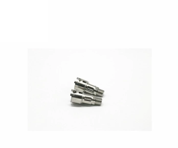
Lock and security hardware is a textbook MIM application, and it is worth understanding why. The parts are small, they carry intricate three-dimensional geometry, they are produced in large and steady volumes, and they must resist wear over hundreds of thousands of cycles. That combination eliminates most competing processes.
It is not a universal answer, though. Many lock components are better served by press-and-sinter powder metallurgy, and a few still belong on a machining centre or in a die caster's hands. This guide sets out the boundaries.
Start with the function, not the part name
Lock hardware vocabulary is functional rather than geometric. A "cam" is the part that converts key rotation into an action; a "latch" is the part that holds the door closed; a "cylinder" is the part that houses the key pins. Two parts with the same name may be a flat stamped plate in one design and a complex three-dimensional forging in another.
This matters because process selection depends on geometry, not on the noun. The productive way to start is to describe what the part does — what it contacts, how it moves, what load it carries, how often it cycles — and then look at the shape that results from that function.
Where MIM fits
MIM belongs on lock components that combine three-dimensional geometry with repeat production volume. In practice, that means:
- Cam and actuator components with radiused working surfaces, integrated bosses or stepped profiles that would need multiple machining setups from bar stock.
- Cylinder and plug-adjacent parts where keyway-side features or internal detail must be formed rather than cut.
- Latch and bolt components with side features, undercuts or engagement geometry that cannot be pressed in a single-axis die.
- Mechanism links, levers and pawls where the shape is genuinely three-dimensional and the annual demand is steady.
- Decorative and functional covers or escutcheons where the geometry includes both mounting detail and an appearance surface.
The common thread is geometry that would be expensive to machine and impossible to press. MIM's advantage in lock work is not that it makes better metal — it is that it removes machining operations from a part that has a lot of them.
Where powder metallurgy fits
A large share of lock hardware is better made by press-and-sinter powder metallurgy. The parts that suit it share one property: their geometry runs along the pressing axis.
- Flat plates and cover plates where thickness is uniform and features are parallel to the pressing direction.
- Plain bushings and bearing sleeves, including oil-impregnated types where designed porosity is an advantage rather than a defect.
- Spacer rings, washers and shims produced in very large quantities at low unit cost.
- Simple gears and pinions where the tooth profile is formed by the die and no cross-holes are required.
- Weights and counterbalance components where density is the main requirement and geometry is simple.
For compaction-friendly lock components, PM may offer an economical route. Compare the complete process, including alloy, density, sizing, machining, heat treatment and surface protection, rather than assuming a universal cost or shrinkage advantage.
Where machining or die casting stays relevant
- Low-volume or bespoke hardware. Architectural and specialty lock work is often produced in tens or hundreds, where no tooling can pay for itself.
- Very large lock bodies and housings. Parts above MIM's practical mass range belong in casting, die casting or machining.
- Components needing tolerances across most dimensions that only machining holds. If the drawing is tolerance-dominated, forming a near-net shape adds cost without removing the machining.
- Zinc and aluminium housings. Where the material is non-ferrous and weight matters, die casting remains the right process.
- Prototypes and design iterations. While the mechanism is still changing, tooling is a liability rather than an investment.
Material and finishing for lock hardware
Lock components are wear parts. They rub, they pivot and they are expected to survive a high cycle count, so material selection is dominated by hardness and corrosion performance rather than by cost alone.
| Requirement | Suitable choice | Notes |
|---|---|---|
| Wear resistance with moderate corrosion | 17-4PH, aged to roughly HRC 30–40 | Good balance for cams, latches and pawls |
| High wear resistance | 420 or 440C, hardened | HRC 48–52 and 58–60 respectively; lower corrosion resistance |
| Corrosion resistance first | 316L with a PVD or electroless nickel coating | Confirm wear, contact pressure and lubrication; a different grade or surface treatment may be needed |
| Cost-sensitive structural parts | Low-alloy steel with black oxide or plating | Needs a coating for corrosion protection |
| Interior mechanism parts | Low-alloy steel, hardened | Where the part is enclosed and corrosion is not a driver |
316L should not be selected from corrosion resistance alone. A rubbing or engagement surface also needs a wear and contact-condition review; a hardenable grade, lubrication strategy or qualified surface treatment may be more appropriate.
Wear life considerations
Cycle-life expectations for lock hardware are high: a commercial lock may be specified for hundreds of thousands of operations. Three factors determine whether a component meets that target.
- Surface hardness at the contact point. Two soft surfaces in sliding contact wear quickly; at least one should be hard, and both should be harder than any abrasive contamination present.
- Surface finish. A smoother working surface reduces wear rate, and MIM parts can be tumbled or, where necessary, machined to achieve it.
- Lubrication and contamination. Whether the mechanism runs dry, greased or exposed to dust changes the wear mechanism entirely — and therefore the material and finish specification.
What to send for a lock program
Lock hardware manufacturers usually know their mechanism well, which means the RFQ can be unusually precise. The most useful package contains: the component drawing with tolerances, a STEP model, the material and hardness requirement, the annual volume and program life, the function of the part and its wear partners, the cycle-life expectation, and the service environment — interior, exterior, or a washdown application.
Cycle-life expectation and service environment are the two fields most often missing, and they are the two that decide both material and finishing. A component destined for an interior cabinet lock and one destined for an exterior padlock may look identical on a drawing and belong in completely different specifications.
Conclusion
Lock hardware is one of the applications where MIM's economics are clearest, because the parts are small, complex and produced in volume, and because machining them involves many operations. Within a lock program, the sensible approach is to route each component to the process that fits its geometry: PM for parts that press cleanly, MIM for parts with three-dimensional detail, and machining for the low-volume or tolerance-dominated exceptions.
The technical decisions that determine success are almost always material and finishing, not the forming process. Choose the grade by asking whether wear or corrosion dominates at the contact point, then specify the hardness range and the surface treatment explicitly.
Related component families
These pages cover the component families that make up most lock and security hardware programs.
Lock and Security Components
Cylinders, cams, latches and mechanism parts produced by MIM and PM.
Component guide →Mechanism Components
Links, levers, pawls and cams where three-dimensional geometry drives the route.
Component guide →Gears and Transmission
Pinions and gear components where PM usually leads on unit cost.
Component guide →Custom OEM Components
Programs where components are specified by function and routed individually.
Component guide →Have a drawing to discuss?
Send it to our engineering team. We review process fit and identify the information needed for a quotation.
Send Drawing for Review