
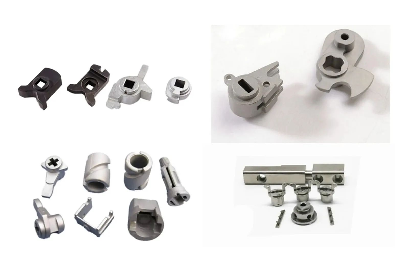
A sensor assembly is a stack of tolerances. The housing locates the core, the core sits at a defined gap from the target, and the output depends on that gap being repeatable across millions of cycles. Every component in the stack is therefore a positioning component, and the requirements placed on them are closer to instrument work than to general hardware.
This guide covers where MIM fits in sensor products, which magnetic materials are available, and the cleanliness and tolerance questions that decide whether a component belongs in a sensor or in a catalog bin.
Where MIM fits in sensor products
MIM enters sensor programs for the same reason it enters other precision programs — small geometry that would need several machining setups — with an additional motivation: sensor parts often need to be produced in large, stable quantities with minimal variation between lots.
Two characteristics of sensors make that combination natural. First, the functional part is often small: a pole piece, a yoke or an armature has a volume measured in cubic centimetres and a feature set that is awkward to machine. Second, sensor performance depends on dimensional repeatability rather than on absolute accuracy, which plays to a moulding process that produces the same part thousands of times.
Typical sensor components
- Pole pieces and cores — geometry that shapes the magnetic field, often with a stepped or rounded profile that is difficult to produce economically by machining.
- Yokes and flux concentrators — parts that carry flux between components, where cross-section and uniformity matter more than absolute dimension.
- Armatures and plungers — moving components in solenoids and actuators, where mass, concentricity and surface finish all interact.
- Housings and carriers — structural parts that locate the sensor element and provide mounting features, including threads and cross-holes.
- Shields and cans — components that manage magnetic or electromagnetic interference, where wall thickness uniformity and material choice are the primary requirements.
Why sensor buyers consider MIM
- Geometry consolidation. A pole piece with a stepped profile, an internal bore and a mounting flange can be produced in one piece instead of several machining operations.
- Repeatability at volume. A mould produces the same geometry thousands of times, and the process window is controlled by the same sintering parameters for every part in the lot.
- Material availability. High-permeability and silicon-iron grades are available as MIM feedstock, which is not true of press-and-sinter PM for many of these compositions.
- Density appropriate to the magnetic and mechanical requirement. MIM typically reaches 95–99% of theoretical density, which supports consistent magnetic cross-section.
- Integration with finishing. Parts can be machined on critical diameters and passivated or coated within the same supply chain.
Magnetic material considerations
Magnetic performance depends on composition, density and microstructure together, which makes material specification more demanding than in structural work.
| Family | Character | Typical use |
|---|---|---|
| Fe-Si (silicon iron) | Higher resistivity reduces eddy current loss; good for alternating fields | AC magnetic circuits, transformer-adjacent components |
| Fe-Ni (high permeability) | Very high permeability; suited to low-field sensitivity | Sensor cores, magnetic shielding |
| Ferritic stainless (430L type) | Combines magnetic response with useful corrosion resistance | Sensor parts exposed to moisture or washdown |
| Low-carbon iron and low-alloy steels | Cost-effective magnetic path where permeability demands are moderate | Yokes, brackets and general flux-carrying parts |
Carbon is the enemy of magnetic performance. Even small amounts retained from incomplete debinding reduce permeability and increase coercivity. The practical implication is that magnetic parts need tighter process control than structural parts, and the specification should state that magnetic performance matters — not just the alloy name.
Where the application depends on a specific value — permeability, saturation induction or core loss — say so, and ask what the supplier can verify. Not every MIM producer runs magnetic property testing in house, and dimensional conformance alone does not demonstrate magnetic conformance.
Tolerance, cleanliness and contamination
Sensor assemblies are less tolerant of contamination than most mechanical assemblies, because a particle in the wrong place changes a magnetic gap or blocks a moving element.
- Define the tolerance that matters. Usually the concentricity of a bore to an outer diameter, the height of a stack, or the flatness of a reference face — not the overall part dimension.
- Specify the cleaning requirement. Whether parts must be free of loose particles, free of oil, or prepared for a cleanroom assembly step changes handling and packaging.
- Specify packaging. Bulk packaging is economical but allows parts to rub together; tray or tube packaging costs more and protects critical surfaces and cleanliness.
- State whether machining is acceptable. Some sensor programs reject any post-sintering cutting on a magnetic component because of the potential for embedded debris or microstructural change; others accept it. This is a requirement to state, not to assume.
When MIM is not the answer
- The magnetic requirement is extreme and the grade is not sinterable to it. Some high-performance alloys are only available in wrought or laminated form.
- The part is a simple cylinder or bushing. Turning produces a round part faster and without tooling cost.
- Annual volume is low. Sensor development often brings design changes; moulds do not welcome them.
- The tolerance is tighter across the whole part than any forming process can hold. If many features need tight control, compare machining with a formed blank plus defined finishing operations before selecting MIM.
- The part is large. Part mass alone does not determine MIM suitability. Review wall sections, flow length, material, distortion risk and complete-route cost against casting or machining.
RFQ details that help
Sensor programs benefit from context. Along with the drawing, STEP model, material and annual volume, include: the function of the part in the assembly, the specific tolerance that governs performance, whether magnetic properties must be demonstrated and how, the cleaning and packaging requirements, and any prohibition on post-sintering machining. That information decides the process window, the inspection plan and the packaging, and it is difficult to add afterwards.
Conclusion
Sensor applications suit MIM when the components are small, geometrically awkward to machine, needed in stable volume and made from a sinterable magnetic grade. What separates a good sensor MIM program from a difficult one is not the geometry — it is whether magnetic performance, cleanliness and the governing tolerance were specified from the start.
Where those requirements are stated, MIM can deliver core and yoke components with consistent magnetic cross-section and repeatable positioning. Where they are left implicit, the program tends to discover them at end-of-line testing, when the cause is hardest to isolate.
Related component families
These pages cover the component types that appear most often in sensor and actuator assemblies.
Precision Small Components
Small parts where repeatability of position drives the specification.
Component guide →Mechanism Components
Armatures, links and levers where mass and concentricity interact.
Component guide →Shafts, Pins and Plungers
Moving components where journal tolerance and finish decide performance.
Component guide →Solenoid and Fluid Control
Application guide for actuator and valve-adjacent components.
Application guide →Have a drawing to discuss?
Send it to our engineering team. We review process fit and identify the information needed for a quotation.
Send Drawing for Review